
Related Manuals for ASROCK IMB-155B


Summary of Contents for ASROCK IMB-155B
- Page 1 IMB-155 User Manual Version 1.1 Published December 2015 Copyright©2015 ASRock INC. All rights reserved.
- Page 2 (including damages for loss of profits, loss of business, loss of data, interruption of business and the like), even if ASRock has been advised of the possibility of such damages arising from any defect or error in the documentation or product.
-
Page 3: Table Of Contents
Contents 1 Introduction ............5 1.1 Package Contents ............5 1.2 Specifications ..............6 1.3 Motherboard Layout ............8 1.4 I/O Panel ................ 10 2 Installation ............11 2.1 Screw Holes ..............11 2.2 Pre-installation Precautions ........... 11 2.3 Installation of Memory Modules (SO-DIMM) ....12 2.4 Expansion Slot ............... - Page 4 4 Software Support ..........37 4.1 Install Operating System ..........37 4.2 Support CD Information ..........37 4.2.1 Running Support CD ..........37 4.2.2 Drivers Menu ............37 4.2.3 Utilities Menu............37 4.2.4 Contact Information ..........37...
-
Page 5: Introduction
In case any modifications of this manual occur, the updated version will be available on ASRock website without further notice. You may find the latest VGA cards and CPU support lists on ASRock website as well. ASRock website http://www.asrock.com If you require technical support related to this motherboard, please visit our website for specific information about the model you are using. -
Page 6: Specifications
1.2 Specifications Form Dimensions Mini-ITX (6.7-in x 6.7-in) Factor ® Intel Pentium/Celeron Braswell SoC Supports Hyper-Threading Technology Default N3150 Quad core 6W processor Core Processor (By CPU, Max 4) Number System Max Speed (By CPU) L2 Cache (By CPU) Chipset (By CPU) BIOS UEFI... - Page 7 4 x USB 3.0 Audio 2 (Mic-in, Line-out) Serial PS/2 4 (2 x 2.0 pitch header USB 2.0 compliant) LVDS/ Inverter 4 x 2.0 pitch header RS-232 (COM1 Serial supports RS-232/RS-422/485) SATA 1 x SATA3 (6.0Gb/s) Internal mPCIe Parallel 1 (Co-lay with 8in/8out DIO) Connector mSATA IrDA...
-
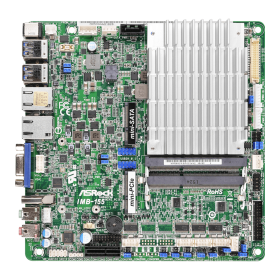
Page 8: Motherboard Layout
1.3 Motherboard Layout DC_JACK1 SATA_1 SATA_PWR1 TO_UPS1 FROM_UPS1 USB 3.0 T: USB1 B: USB0 USB3_PWR1 USB 3.0 USB3_PWR2 BIOS T: USB3 Chip B: USB2 LAN1 LAN2 USB2H_0_1 USB_PWR_H1 CPU_FAN1 USB_PWR_H2 USB2H_2_3 DDR3_B1 (Support DDR3L Only) VGA_H1 PANEL1 DDR3_A1 (Support DDR3L Only) HDMI1 Industrial IMB-155... - Page 9 1 : 2-pin UPS Module Power Input Connector 2 : ATX Power Connector (Input 12V or 19~24V) 3 : SATA Power Output Connector 4 : SATA3 Connector (SATA_1) 5 : LVDS Panel Connector 6 : BLT_PWM1 7 : Backlight Volume Control (BLT_VOL1) 8 : Backlight Power Connector (BLT_PWR1) 9 : Backlight Power Select (LCD_BLT_VCC) (BKT_PWR1) 10 : Panel Power Selection (LCD_VCC) (PNL_PWR1)
-
Page 10: I/O Panel
1.4 I/O Panel DC Jack VGA Port (VGA1) USB 3.0 Ports (USB3_0_1) HDMI Port (HDMI1) USB 3.0 Ports (USB3_2_3) Line out (Green) LAN RJ-45 Port* Microphone (Pink) LAN RJ-45 Port* * There are two LED next to the LAN port. Please refer to the table below for the LAN port LED indications. -
Page 11: Installation
Chapter 2: Installation This is a Mini-ITX form factor (6.7" x 6.7", 17.0 x 17.0 cm) motherboard. Before you install the motherboard, study the configuration of your chassis to ensure that the motherboard fits into it. Make sure to unplug the power cord before installing or removing the motherboard. -
Page 12: Installation Of Memory Modules (So-Dimm)
2.3 Installation of Memory Modules (SO-DIMM) IMB-155 motherboard provides two 204-pin DDR3 (Double Data Rate 3) SO-DIMM slots, which support Dual Channel DDR3L (low voltage). 1. If you install one memory module only, please install it on DDR3_A1. 2. It is not allowed to install a DDR or DDR2 memory module into a DDR3 slot;... -
Page 13: Expansion Slot
2.4 Expansion Slots (mini-PCIe, mini-SATA and PCI Express Slots) There is 1 mini-PCIe slot, 1 mini-SATA slot and 1 PCI Express slot on this mother- board. mini-PCIe slot: MINI_PCIE1 (mini-PCIe slot; half size) is used for PCI Express mini cards. mini-SATA slot: MINI_SATA1 (mini-SATA slot;... -
Page 14: Jumpers Setup
2.5 Jumpers Setup The illustration shows how jumpers are setup. When the jumper cap is placed on pins, the jumper is “Short”. If no jumper cap is placed on pins, the jumper is “Open”. The illustration shows a 3-pin jumper whose pin1 and pin2 are “Short”... - Page 15 Backlight Power Select Use this to set up the backlight (LCD_BLT_VCC) power of the LVDS connector and the panel backlight power (5-pin BKT_PWR1) of BLT_PWM1. (see p.8 No. 9) 1-2: LCD_BLT_VCC: +5V 2-3: LCD_BLT_VCC: +12V 4-5: LCD_BLT_VCC: DC_IN Backlight Control Level (CON_LBKLT_CTL) 1-2: +3V Level 2-3: +5V Level (3-pin BLT_PWM1)
- Page 16 Digital Input / Output Default Value Setting 1-2: Pull-High 2-3: Pull-Low (3-pin JGPIO_SET1) (see p.8, No. 15)
-
Page 17: Onboard Headers And Connectors
2.6 Onboard Headers and Connectors Onboard headers and connectors are NOT jumpers. Do NOT place jumper caps over these headers and connectors. Placing jumper caps over the headers and connectors will cause permanent damage of the motherboard! SATA3 Connector This Serial ATA3 (SATA3) connector supports (SATA_1: see p.8, No. - Page 18 HDLED (Hard Drive Activity LED): Connect to the hard drive activity LED on the chassis front panel. The LED is on when the hard drive is reading or writing data. The front panel design may differ by chassis. A front panel module mainly consists of power switch, reset switch, power LED, hard drive activity LED, speaker and etc.
- Page 19 CPU Fan Connector Please connect the CPU fan FAN_SPEED_CONTROL cable to the connector and (4-pin CPU_FAN1) FAN_SPEED match the black wire to the (see p.8 No. 11) +12V ground pin. Though this motherboard provides 4-Pin CPU fan (Quiet Fan) support, the 3-Pin CPU fan still can work successfully even without the fan speed control function.
- Page 20 LVDS Connector Signal Name Signal Name LCD_VCC LCD_VCC (40-pin LVDS1) LDDC_CLK +3.3V (see p.8 No. 5) LVDS_A_DATA0# LDDC_DATA LVDS_A_DATA0 LVDS_A_DATA1 LVDS_A_DATA1# LVDS_A_DATA2# LVDS_A_DATA2 LVDS_A_DATA3 LVDS_A_DATA3# LVDS_A_CLK# LVDS_A_CLK LVDS_B_DATA0 LVDS_B_DATA0# LVDS_B_DATA1# LVDS_B_DATA1 LVDS_B_DATA2 LVDS_B_DATA2# LVDS_B_DATA3# DPLVDD_EN LVDS_B_DATA3 LVDS_B_CLK LVDS_B_CLK# CON_LBKLT_EN LCD_BLT_VCC CON_LBKLT_CTL LCD_BLT_VCC LCD_BLT_VCC...
- Page 21 Chassis Intrusion Headers This motherboard supports CASE OPEN detection feature (2-pin CI1, CI2: see p.8, No. 18) that detects if the chassis cover Signal has been removed. This feature requires a chassis with chassis intrusion detection design. COM1 Header (RS232/422/485) (9-pin COM1: see p.8, No.
- Page 22 SPDIF Header DUMMY (3-pin SPDIF1: see p.8, No. 24) SPDIF OUT VGA Header (10-pin VGA1: see p.8, No. 29) Signal Signal Signal Signal Signal Name Name Name Name Name 10 DDC_DATA 8 VSYNC DDC_CLK HSYNC BLUE GREEN UPS Module Power Input Connector Pin1: GND Pin2: DC Input (2-pin TO_UPS1: see p.8, No.
-
Page 23: Uefi Setup Utility
Chapter 3: UEFI SETUP UTILITY 3.1 Introduction This section explains how to use the UEFI SETUP UTILITY to configure your system. The UEFI chip on the motherboard stores the UEFI SETUP UTILITY. You may run the UEFI SETUP UTILITY when you start up the computer. Please press <F2>... -
Page 24: Navigation Keys
3.1.2 Navigation Keys Please check the following table for the function description of each navigation key. Navigation Key(s) Function Description Moves cursor left or right to select Screens Moves cursor up or down to select items + / - To change option for the selected items <Enter>... -
Page 25: Advanced Screen
3.3 Advanced Screen In this section, you may set the configurations for the following items: CPU Configu- ration, Chipset Configuration, Storage Configuration, Super IO Configuration, ACPI Configuration and USB Configuration. Setting wrong values in this section may cause the system to malfunction. Instant Flash Instant Flash is a UEFI flash utility embedded in Flash ROM. -
Page 26: Cpu Configuration
3.3.1 CPU Configuration Intel SpeedStep Technology Intel SpeedStep technology is Intel’s new power saving technology. Pro- cessors can switch between multiple frequencies and voltage points to en- able power saving. The default value is [Enabled]. Configuration options: ® [Enabled] and [Disabled]. If you install Windows 8 / 8.1 and want to en- able this function, please set this item to [Enabled]. -
Page 27: Chipset Configuration
3.3.2 Chipset Configuration Primary Graphics Adapter This allows you to select [Onboard] or [PCI Express] as the boot graphic adapter priority. The default value is [PCI Express]. Share Memory Configure the size of memory that is allocated to the integrated graphics processor when the system boots up. -
Page 28: Storage Configuration
3.3.3 Storage Configuration SATA Controller(s) Use this item to enable or disable the SATA Controller feature. SATA Mode Selection Use this to select SATA mode. The default value is [AHCI Mode]. AHCI (Advanced Host Controller Interface) supports NCQ and other new features that will improve SATA disk perfor- mance but IDE mode does not have these advantages. -
Page 29: Super Io Configuration
3.3.4 Super IO Configuration COM1 Configuration Use this to set parameters of COM1. Select COM1 port type: [RS232], [RS422] or [RS485]. COM4 Configuration Use this to set parameters of COM4. COM5 Configuration Use this to set parameters of COM5. COM6 Configuration Use this to set parameters of COM6. -
Page 30: Acpi Configuration
3.3.5 ACPI Configuration Suspend to RAM Use this item to select whether to auto-detect or disable the Suspend-to- RAM feature. Select [Auto] will enable this feature if the OS supports it. ACPI HPET Table Use this item to enable or disable ACPI HPET Table. The default value is [Enabled]. -
Page 31: Usb Configuration
3.3.6 USB Configuration Legacy USB Support Use this option to select legacy support for USB devices. There are four configuration options: [Enabled], [Auto] and [UEFI Setup Only]. The default value is [Auto]. Please refer to below descriptions for the details of these four options: [Enabled] - Enables support for legacy USB. -
Page 32: Hardware Health Event Monitoring Screen
3.4 Hardware Health Event Monitoring Screen In this section, it allows you to monitor the status of the hardware on your system, including the parameters of the CPU temperature, motherboard temperature, CPU fan speed, chassis fan speed, and the critical voltage. CPU_FAN1 Setting This allows you to set CPU_FAN1’s speed. -
Page 33: Security Screen
3.5 Security Screen In this section, you may set, change or clear the supervisor/user password for the system. Supervisor Password Set or change the password for the administrator account. Only the ad- ministrator has authority to change the settings in the UEFI Setup Utility. Leave it blank and press enter to remove the password. -
Page 34: Boot Screen
3.6 Boot Screen In this section, it will display the available devices on your system for you to config- ure the boot settings and the boot priority. Fast Boot Fast Boot minimizes your computer’s boot time. There are three con- figuration options: [Disabled], [Fast] and [Ultra Fast]. - Page 35 Full Screen Logo Use this item to enable or disable OEM Logo. The default value is [Enabled]. CSM (Compatibility Support Module) Enable to launch the Compatibility Support Module. Please do not disable ® unless you’re running a WHCK test. If you are using Windows 8 64-bit and all of your devices support UEFI, you may also disable CSM for faster boot speed.
-
Page 36: Exit Screen
3.7 Exit Screen Save Changes and Exit When you select this option, it will pop-out the following message, “Save configuration changes and exit setup?” Select [OK] to save the changes and exit the UEFI SETUP UTILITY. Discard Changes and Exit When you select this option, it will pop-out the following message, “Discard changes and exit setup?”... - Page 37 Click on a specific item then follow the installation wizard to install it. 4.2.4 Contact Information If you need to contact ASRock or want to know more about ASRock, you’re welcome to visit ASRock’s website at http://www.asrock.com; or you may con-...
Need help?
Do you have a question about the IMB-155B and is the answer not in the manual?
Questions and answers