Sign In
Upload
Download
Table of Contents
Contents
Add to my manuals
Delete from my manuals
Share
URL of this page:
HTML Link:
Bookmark this page
Add
Manual will be automatically added to "My Manuals"
Print this page
×
Bookmark added
×
Added to my manuals
Manuals
Brands
ASROCK Manuals
Motherboard
IMB-150N
User manual
ASROCK IMB-150N User Manual
Hide thumbs
1
2
Table Of Contents
3
4
5
6
7
8
9
10
11
12
13
14
15
16
17
18
19
20
21
22
23
24
25
26
27
28
29
30
31
32
33
34
35
36
37
38
39
page
of
39
Go
/
39
Contents
Table of Contents
Bookmarks
Table of Contents
Table of Contents
Introduction
Package Contents
Specifications
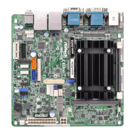
Motherboard Layout
I/O Panel
Installation
Screw Holes
Pre-Installation Precautions
Installation of Memory Modules (SO-DIMM)
Expansion Slot
Jumpers Setup
Onboard Headers and Connectors
Uefi Setup Utility
Introduction
UEFI Menu Bar
Navigation Keys
Main Screen
Advanced Screen
CPU Configuration
Chipset Configuration
Storage Configuration
Intel(R) Smart Connect Technology
Super IO Configuration
ACPI Configuration
USB Configuration
Hardware Health Event Monitoring Screen
Security Screen
Boot Screen
Exit Screen
Advertisement
Quick Links
Download this manual
IMB-150
User Manual
Version 1.2
Published November 2014
Copyright©2014 ASRock INC. All rights reserved.
1
Table of
Contents
Previous
Page
Next
Page
1
2
3
4
5
Advertisement
Table of Contents
Need help?
Do you have a question about the IMB-150N and is the answer not in the manual?
Ask a question
Questions and answers
Related Manuals for ASROCK IMB-150N
Motherboard ASRock IMB-150 User Manual
(39 pages)
Motherboard ASROCK IMB-150 Settings Manual
Jumpers and headers (2 pages)
Motherboard ASROCK IMB-150D User Manual
(39 pages)
Motherboard ASROCK IMB-150D-PCI User Manual
(40 pages)
Motherboard Asrock IMB-152 User Manual
(37 pages)
Motherboard ASROCK IMB-153 User Manual
(40 pages)
Motherboard ASROCK IMB-151 User Manual
(38 pages)
Motherboard ASROCK IMB-151N User Manual
(38 pages)
Motherboard ASROCK IMB-157 User Manual
(38 pages)
Motherboard ASROCK IMB-157J User Manual
(39 pages)
Motherboard ASROCK IMB-156 User Manual
(37 pages)
Motherboard ASROCK IMB-156J User Manual
(37 pages)
Motherboard ASROCK IMB-158 User Manual
(40 pages)
Motherboard ASROCK IMB-155B User Manual
(37 pages)
Motherboard ASROCK IMB-154 User Manual
(38 pages)
Motherboard ASROCK IMB-154B User Manual
(38 pages)
This manual is also suitable for:
Imb-150
Imb-150d
Table of Contents
Print
Rename the bookmark
Delete bookmark?
Delete from my manuals?
Login
Sign In
OR
Sign in with Facebook
Sign in with Google
Upload manual
Upload from disk
Upload from URL


Need help?
Do you have a question about the IMB-150N and is the answer not in the manual?
Questions and answers