
Related Manuals for ASROCK SBC-310


Summary of Contents for ASROCK SBC-310
- Page 1 SBC-310 SBC-311 User Manual Version 1.0 Published February 2015 Copyright©2015 ASRock INC. All rights reserved.
- Page 2 (including damages for loss of profits, loss of business, loss of data, interruption of business and the like), even if ASRock has been advised of the possibility of such damages arising from any defect or error in the documentation or product.
-
Page 3: Table Of Contents
Contents 1 Introduction ............5 1.1 Package Contents ............5 1.2 Specifications ..............6 1.3 Motherboard Layout ............8 1.4 I/O Panel ................ 10 2 Installation ............11 2.1 Screw Holes ..............11 2.2 Pre-installation Precautions ........... 11 2.3 Installation of Memory Modules (SO-DIMM) ....12 2.4 Expansion Slots (mini-PCIe and mini-PCIe/mini-SATA Slots) ................ - Page 4 4 Software Support ..........41 4.1 Install Operating System ..........41 4.2 Support CD Information ..........41 4.2.1 Running Support CD ..........41 4.2.2 Drivers Menu ............41 4.2.3 Utilities Menu............41 4.2.4 Contact Information ..........41...
-
Page 5: Introduction
In case any modifications of this manual occur, the updated version will be available on ASRock website without further notice. You may find the latest VGA cards and CPU support lists on ASRock website as well. ASRock website http://www.asrock.com If you require technical support related to this motherboard, please visit our website for specific information about the model you are using. -
Page 6: Specifications
1.2 Specifications Form Dimensions 3.5” SBC (5.8-in x 4.0-in) / (146 x 102 mm) Factor SBC-310: ® BGA type for Intel Core i7-4650/i5-4300U Haswell ULT Quad/Dual core MCP processor SBC-311: ® ® BGA type for Intel Core i3-4010/ Celeron Processor... - Page 7 Max Data SATA Transfer SATA3 (6.0Gb/s) Rate HDMI DVI-I/D DisplayPort 0 Ethernet Rear I/O 4 x USB 3.0 Audio Serial e-SATA PS/2 4 (2 x USB Header 2.54mm pitch) LVDS/ 24 bit dual channel LVDS co-lay with eDP Inverter Serial 4 (2 RS-232/422/485, 2 RS-232) SATA 2 x SATA3 (6.0Gb/s)
-
Page 8: Motherboard Layout
1.3 Motherboard Layout BIOS DDR3 (Support DDR3L Only) Chip CLRMOS1 USB 3.0 FAN1 T: USB1 B: USB0 MSATA_SEL1 BUZZ1 USB 3.0 T: USB3 B: USB2 USB6_7 USB8_9 HDMI1 HDMI2 BLT_PWM1 SATA3_2 BKT_PWR1 LAN1 SATA3_1 PNL_PWR1 LAN2 SATA_PWR1 HD_AUDIO1 PWR_COM4 PWR_JP1 SPEAKER1 LPC1 PWR_COM1... - Page 9 1 : Clear CMOS Header 2 : 4-Pin FAN Connector (+12V) 3 : mSATA Select 4 : 2-Pin Buzzer Header 5 : USB2.0 Headers (USB6_7, USB8_9) 6 : Backlight & Amp Volume Control (BLT_VOL1) 7 : Inverter Power Control Wafer (BLT_PWR1) 8 : Backlight Control Level (BLT_PWM1) 9 : Backlight Power Select (LCD_BLT_VCC) (BKT_PWR1) 10 : SATA3 Connectors (SATA3_1, SATA3_2)
-
Page 10: I/O Panel
1.4 I/O Panel USB 3.0 Ports (USB01) HDMI Port (HDMI2) USB 3.0 Ports (USB23) LAN RJ-45 Port (LAN1)* HDMI Port (HDMI1) LAN RJ-45 Port (LAN2)* * There are two LED next to the LAN port. Please refer to the table below for the LAN port LED indications. -
Page 11: Installation
Chapter 2: Installation This is a 3.5” SBC (5.8-in x 4.0-in) form factor (146 x 102 mm) motherboard. Before you install the motherboard, study the configuration of your chassis to ensure that the motherboard fits into it. Make sure to unplug the power cord before installing or removing the motherboard. -
Page 12: Installation Of Memory Modules (So-Dimm)
2.3 Installation of Memory Modules (SO-DIMM) SBC-310 / SBC-311 provides one 204-pin DDR3 (Double Data Rate 3) SO-DIMM slot, which supports single channel DDR3L SDRAM only. Step 1. Align a SO-DIMM on the slot such that the notch on the SO-DIMM matches the break on the slot. -
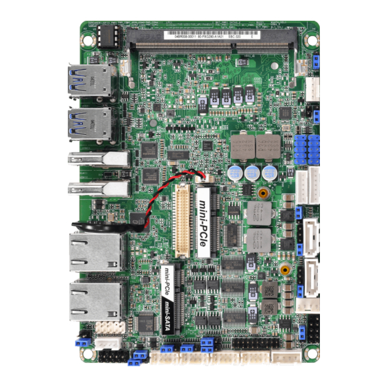
Page 13: Expansion Slots (Mini-Pcie And Mini-Pcie/Mini-Sata Slots)
2.4 Expansion Slots (mini-PCIe and mini-PCIe/mini-SATA Slots) There is 1 mini-PCIe slot and 1 mini-PCIe/mini-SATA slot on this motherboard. mini-PCIe slot: MINI_PCIE1 (mini-PCIe slot; half size) is used for PCI Express mini cards. mini-PCIe/mini-SATA slot: MINI_PCIE2 (mini-PCIe/mini-SATA slot; full size) is used for PCI Ex- press mini cards or mSATA cards. -
Page 14: Jumpers Setup
2.5 Jumpers Setup The illustration shows how jumpers are setup. When the jumper cap is placed on pins, the jumper is “Short”. If no jumper cap is placed on pins, the jumper is “Open”. The illustration shows a 3-pin jumper whose pin1 and pin2 are “Short”... - Page 15 Backlight Power Select Use this to set up the backlight (LCD_BLT_VCC) power of the LVDS connector. 1-2: +5V (5-pin BKT_PWR1) 2-3: +12V (see p.8 No. 9) 3-4: +12V 4-5: DC_IN Power Backlight Control Level 1-2: +3V 2-3: +5V (3-pin BLT_PWM1) (see p.8 No.
-
Page 16: Onboard Headers And Connectors
2.6 Onboard Headers and Connectors Onboard headers and connectors are NOT jumpers. Do NOT place jumper caps over these headers and connectors. Placing jumper caps over the headers and connectors will cause permanent damage of the motherboard! SATA3 Connectors These two Serial ATA3 SATA3_2 (SATA3) connectors support (SATA3_1, SATA3_2: see p.8, No. - Page 17 HDLED (Hard Drive Activity LED): Connect to the hard drive activity LED on the chassis front panel. The LED is on when the hard drive is reading or writing data. The front panel design may differ by chassis. A front panel module mainly consists of power switch, reset switch, power LED, hard drive activity LED, speaker and etc.
- Page 18 COM Port Headers (10-pin COM1) (see p.8 No. 23) (10-pin COM2) (see p.8 No. 21) (10-pin COM3) Signal Signal Signal Signal Signal Name Name Name Name Name (see p.8 No. 19) DUMMY CCTS# DDSR# DDTR# RRXD (10-pin COM4) DUMMY RRTS# TTXD DDCD# (see p.8 No.
- Page 19 LVDS Connector Signal Name Signal Name LCD_VCC LCD_VCC (40-pin LVDS1) LDDC_CLK +3.3V (see p.8 No. 31) LVDS_A_DATA0# LDDC_DATA LVDS_A_DATA0 LVDS_A_DATA1 LVDS_A_DATA1# LVDS_A_DATA2# LVDS_A_DATA2 LVDS_A_DATA3 LVDS_A_DATA3# LVDS_A_CLK# LVDS_A_CLK LVDS_B_DATA0 LVDS_B_DATA0# LVDS_B_DATA1# LVDS_B_DATA1 LVDS_B_DATA2 LVDS_B_DATA2# LVDS_B_DATA3# DPLVDD_EN LVDS_B_DATA3 LVDS_B_CLK LVDS_B_CLK# CON_LBKLT_EN LCD_BLT_VCC CON_LBKLT_CTL LCD_BLT_VCC LCD_BLT_VCC...
- Page 20 LPC Header This connector supports Trusted Platform Module (TPM) (19-pin LPC1) system, which can securely (see p.8 No. 16) store keys, digital certificates, passwords, and data. A TPM system also helps enhance network security, protects digital identities, and ensures platform integrity.
-
Page 21: Uefi Setup Utility
Chapter 3: UEFI SETUP UTILITY 3.1 Introduction This section explains how to use the UEFI SETUP UTILITY to configure your system. The UEFI chip on the motherboard stores the UEFI SETUP UTILITY. You may run the UEFI SETUP UTILITY when you start up the computer. Please press <F2>... -
Page 22: Navigation Keys
To save changes and exit the UEFI SETUP UTILITY <F12> Print screen <ESC> To jump to the Exit Screen or exit the current screen 3.2 Main Screen When you enter the UEFI SETUP UTILITY, the Main screen will appear and display the system overview. SBC-310... - Page 23 SBC-311...
-
Page 24: Advanced Screen
3.3 Advanced Screen In this section, you may set the configurations for the following items: CPU Configu- ration, Chipset Configuration, Storage Configuration, Intel(R) Rapid Start Technol- ogy, AMT Configuration, Super IO Configuration, ACPI Configuration, USB Configu- ration and Voltage Configuration. Setting wrong values in this section may cause the system to malfunction. -
Page 25: Cpu Configuration
3.3.1 CPU Configuration Intel Hyper Threading Technology To enable this feature, a computer system with an Intel processor that sup- ports Hyper-Threading technology and an operating system that includes ® ® optimization for this technology, such as Microsoft Windows 7 / 8 is re- ®... - Page 26 ® [Enabled] and [Disabled]. If you install Windows 7 / 8 and want to enable this function, please set this item to [Enabled]. This item will be hidden if the current CPU does not support Intel SpeedStep technology. Please note that enabling this function may reduce CPU voltage and lead to system stability or compatibility issues with some power supplies.
-
Page 27: Chipset Configuration
3.3.2 Chipset Configuration DRAM Frequency If [Auto] is selected, the motherboard will detect the memory module(s) inserted and assign the appropriate frequency automatically. VT-d ® Intel Virtualization Technology for Directed I/O helps your virtual machine monitor better utilize hardware by improving application compatibility and reliability, and providing additional levels of manageability, security, isola- tion, and I/O performance. - Page 28 Onboard LAN 2 (Realtek) This allows you to enable or disable the Onboard LAN 2 feature. Deep Sleep Mobile platforms support Deep S4/S5 in DC only and desktop platforms support Deep S4/S5 in AC only. The default value is [Disabled]. Restore on AC/Power Loss This allows you to set the power state after an unexpected AC/power loss.
-
Page 29: Storage Configuration
3.3.3 Storage Configuration SATA Controller(s) Use this item to enable or disable the SATA Controller feature. SATA Mode Selection Use this to select SATA mode. Configuration options: [IDE Mode] and [AHCI Mode]. The default value is [AHCI Mode]. AHCI (Advanced Host Controller Interface) supports NCQ and other new features that will improve SATA disk perfor- mance but IDE mode does not have these advantages. -
Page 30: Intel(R) Rapid Start Technology
3.3.4 Intel(R) Rapid Start Technology Intel(R) Rapid Start Technology Use this item to enable or disable Intel(R) Rapid Start Technology. Intel(R) Rapid Start Technology is a new zero power hibernation mode which al- lows users to resume in just 5-6 seconds. The default is [Disabled]. -
Page 31: Amt Configuration
3.3.5 AMT Configuration Intel AMT Use this to enable or disable Intel(R) Active Management Technology. BIOS Hotkey Pressed Use this to enable or disable BIOS Hotkey Pressed. MEBx Selection Screen Use this to enable or disable MEBx selection screen. Hide Un-Configure ME Configuration Use this to hide Un-Configure ME without password confirmation prompt. -
Page 32: Super Io Configuration
3.3.6 Super IO Configuration COM1 Configuration Use this to set parameters of COM1. Select COM1 port type: [RS232], [RS422] or [RS485]. COM2 Configuration Use this to set parameters of COM2. Select COM2 port type: [RS232], [RS422] or [RS485]. COM3 Configuration Use this to set parameters of COM3. -
Page 33: Acpi Configuration
3.3.7 ACPI Configuration Suspend to RAM Use this item to select whether to auto-detect or disable the Suspend-to- RAM feature. Select [Auto] will enable this feature if the OS supports it. ACPI HPET Table Use this item to enable or disable ACPI HPET Table. The default value is [Enabled]. -
Page 34: Usb Configuration
3.3.8 USB Configuration USB Controller Use this item to enable or disable the use of USB controller. Intel USB 3.0 Mode Use this item to enable or disable the use of Intel USB 3.0 mode. Legacy USB Support Use this option to select legacy support for USB devices. There are four configuration options: [Enabled], [Auto] and [UEFI Setup Only]. -
Page 35: Voltage Configuration
3.3.9 Voltage Configuration DRAM Voltage Use this to select DRAM Voltage. The default value is [Auto]. -
Page 36: Hardware Health Event Monitoring Screen
3.4 Hardware Health Event Monitoring Screen In this section, it allows you to monitor the status of the hardware on your system, including the parameters of the CPU temperature, motherboard temperature, CPU fan speed, chassis fan speed, and the critical voltage. FAN1 Setting This allows you to set fan 1’s speed. -
Page 37: Boot Screen
3.5 Boot Screen In this section, it will display the available devices on your system for you to config- ure the boot settings and the boot priority. Boot From Onboard LAN Use this item to enable or disable the Boot From Onboard LAN feature. Setup Prompt Timeout This shows the number of seconds to wait for setup activation key. - Page 38 CSM (Compatibility Support Module) Enable to launch the Compatibility Support Module. Please do not disable ® unless you’re running a WHCK test. If you are using Windows 8 64-bit and all of your devices support UEFI, you may also disable CSM for faster boot speed.
-
Page 39: Security Screen
3.6 Security Screen In this section, you may set, change or clear the supervisor/user password for the system. Supervisor Password Set or change the password for the administrator account. Only the ad- ministrator has authority to change the settings in the UEFI Setup Utility. Leave it blank and press enter to remove the password. -
Page 40: Exit Screen
3.7 Exit Screen Save Changes and Exit When you select this option, it will pop-out the following message, “Save configuration changes and exit setup?” Select [OK] to save the changes and exit the UEFI SETUP UTILITY. Discard Changes and Exit When you select this option, it will pop-out the following message, “Discard changes and exit setup?”... - Page 41 Click on a specific item then follow the installation wizard to install it. 4.2.4 Contact Information If you need to contact ASRock or want to know more about ASRock, you’re welcome to visit ASRock’s website at http://www.asrock.com; or you may con-...
Need help?
Do you have a question about the SBC-310 and is the answer not in the manual?
Questions and answers