
Subscribe to Our Youtube Channel
Related Manuals for ASROCK SBC-230-WT


Summary of Contents for ASROCK SBC-230-WT
- Page 1 SBC-230-WT SBC-230D SBC-230L SBC-E230 SBC-230J User Manual Version 1.0 Published May 2017 Copyright©2017 ASRock INC. All rights reserved.
- Page 2 (including damages for loss of profits, loss of business, loss of data, interruption of business and the like), even if ASRock has been advised of the possibility of such damages arising from any defect or error in the documentation or product.
- Page 3 ® The terms HDMI and HDMI High-Definition Multimedia Interface, and the HDMI logo are trademarks or registered trademarks of HDMI Licensing LLC in the United States and other countries. CAUTION: RISK OF EXPLOSION IF BATTERY IS REPLACED BY AN INCORRECT TYPE. DISPOSE OF USED BATTERIES ACCORDING TO THE INSTRUCTIONS.
-
Page 4: Table Of Contents
Contents 1 Introduction ............5 1.1 Package Contents ............5 1.2 Specifications ..............6 1.3 Motherboard Layout ............8 1.4 I/O Panel ................ 10 2 Installation ............11 2.1 Screw Holes ..............11 2.2 Pre-installation Precautions ........... 11 2.3 Installation of Memory Modules (SO-DIMM) ....12 2.4 Expansion Slots ............. -
Page 5: Introduction
Chapter 1: Introduction Thank you for purchasing ASRock SBC-230-WT / SBC-230D / SBC-230L / SBC- E230 / SBC-230J motherboard, a reliable motherboard produced under ASRock’s consistently stringent quality control. It delivers excellent performance with robust design conforming to ASRock’s commitment to quality and endurance. -
Page 6: Specifications
1.2 Specifications Form Dimensions 3.5” SBC (5.8-in x 4.0-in) / (146 x 102 mm) Factor SBC-230-WT / SBC-230D / SBC-230L / SBC- ® 230J: BGA1296 for Intel Apollo Lake SoC (N4200/N3350) ® SBC-E230: BGA1296 for Intel Apollo Lake SoC (E3950/E3940/E3930) - Page 7 HDMI DisplayPort 0 Rear I/O Ethernet 2 (USB 3.0) Audio 2 (Mic-in, Line-out) Serial PS/2 4 x USB 2.0 (2 x 2.54 pitch header) LVDS/ Inverter Serial 4 x COM (COM1 supports RS-232/422/485) SATA Internal mPCIe Connector Parallel mSATA 1 (shared with mini-PCIe) IrDA GPIO 8-bit 4 x GPI + 4 x GPO...
-
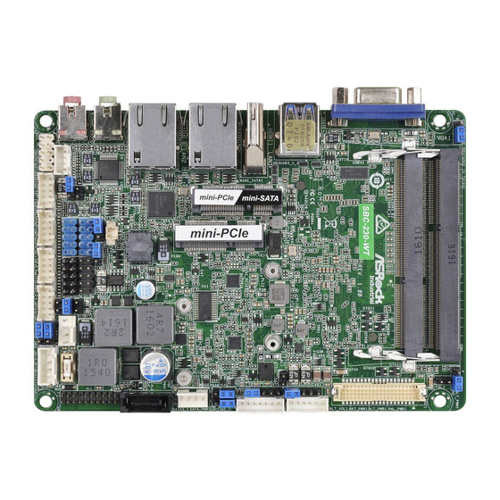
Page 8: Motherboard Layout
1.3 Motherboard Layout EDP_LVDS_J2 DDR3_B1 (Support DDR3L Only) DDR3_A1 (Support DDR3L Only) Industrial SBC-230 USB 3.0 T: USB3 B: USB2 HDMI1 LAN1 LAN2 BIOS Chip Line Out MSATA_SEL1 JGPIO_PWR1 PANEL1 PLED PWRBTN USB2_6_7 HDLED RESET JGPIO1 BUZZ1 Mic In FAN1 SET_CM1 USB2_4_5 SPEAKER1... - Page 9 1 : EDP_LVDS_J2 2 : BL2 3 : LVDS Panel Connector * eDP Connector (on the Backside of PCB) 4 : BL1 5 : Panel Power Selection (LCD_VCC) (PNL_PWR1) 6 : Inverter Power Control Wafer (BLT_PWR1) 7 : Backlight Power Select (LCD_BLT_VCC) (BKT_PWR1) 8 : Backlight &...
-
Page 10: I/O Panel
1.4 I/O Panel D-Sub Port (VGA1) LAN RJ-45 Port (LAN2)* USB 3.0 Ports (USB3_2_3) Line Out (Green) HDMI Port (HDMI1) Microphone (Pink) LAN RJ-45 Port (LAN1)* * There are two LED next to the LAN port. Please refer to the table below for the LAN port LED indications. -
Page 11: Installation
Chapter 2: Installation This is a 3.5” SBC (5.8-in x 4.0-in) form factor (146 x 102 mm) motherboard. Before you install the motherboard, study the configuration of your chassis to ensure that the motherboard fits into it. Make sure to unplug the power cord before installing or removing the motherboard. -
Page 12: Installation Of Memory Modules (So-Dimm)
2.3 Installation of Memory Modules (SO-DIMM) SBC-230-WT / SBC-230D / SBC-230L / SBC-E230 / SBC-230J provides two 204- pin DDR3 (Double Data Rate 3) SO-DIMM slots. Step 1. Align a SO-DIMM on the slot such that the notch on the SO-DIMM matches the break on the slot. -
Page 13: Expansion Slots
2.4 Expansion Slots (mini-PCIe and mini-PCIe/mini-SATA Slots) There is 1 mini-PCIe slot and 1 mini-PCIe/mini-SATA slot on this motherboard. mini-PCIe slot: MINI_PCIE1 (mini-PCIe slot; full size) is used for PCI Express mini cards. mini-PCIe/mini-SATA slot: MINI_SATA1 (mini-PCIe/mini-SATA slot; full size) is used for PCI Ex- press mini cards or mSATA cards. -
Page 14: Jumpers Setup
2.5 Jumpers Setup The illustration shows how jumpers are setup. When the jumper cap is placed on pins, the jumper is “Short”. If no jumper cap is placed on pins, the jumper is “Open”. The illustration shows a 3-pin jumper whose pin1 and pin2 are “Short”... - Page 15 ATX/AT Mode Select 1-2: AT Mode 2-3: ATX Mode (3-pin PWR_JP1) (see p.8 No. 10) Panel Power Select (LCD_VCC) Use this to set up the VDD power of the LVDS connector. (5-pin PNL_PWR1) 1-2: +3V (see p.8 No. 5) 2-3: +5V 3-4: +5V 4-5: +12V Backlight Power Select...
-
Page 16: Onboard Headers And Connectors
2.6 Onboard Headers and Connectors Onboard headers and connectors are NOT jumpers. Do NOT place jumper caps over these headers and connectors. Placing jumper caps over the headers and connectors will cause permanent damage of the motherboard! SATA3 Connector This Serial ATA3 (SATA3) connector supports (SATA3_1: see p.8, No. - Page 17 HDLED (Hard Drive Activity LED): Connect to the hard drive activity LED on the chassis front panel. The LED is on when the hard drive is reading or writing data. The front panel design may differ by chassis. A front panel module mainly consists of power switch, reset switch, power LED, hard drive activity LED, speaker and etc.
- Page 18 COM Port Headers (10-pin COM1~4) (see p.8 No. 24) Signal Signal Signal Signal PIN Signal Name Name Name Name Name DDCD# TTXD RRTS# COM_PWR RRXD DDTR# DDSR# CCTS# DUMMY This motherboard supports RS232/422/485 on COM1 port. Please refer to below table for the pin definition. In addition, COM1 port (RS232/422/485) can be adjusted in BIOS setup utility >...
- Page 19 LVDS Connector Signal Name Signal Name LCD_VCC LCD_VCC (40-pin LVDS1) LDDC_CLK +3.3V (see p.8 No. 3) LVDS_A_DATA0# LDDC_DATA LVDS_A_DATA0 LVDS_A_DATA1 LVDS_A_DATA1# LVDS_A_DATA2# LVDS_A_DATA2 LVDS_A_DATA3 LVDS_A_DATA3# LVDS_A_CLK# LVDS_A_CLK LVDS_B_DATA0 LVDS_B_DATA0# LVDS_B_DATA1# LVDS_B_DATA1 LVDS_B_DATA2 LVDS_B_DATA2# LVDS_B_DATA3# DPLVDD_EN LVDS_B_DATA3 LVDS_B_CLK LVDS_B_CLK# CON_LBKLT_EN LCD_BLT_VCC CON_LBKLT_CTL LCD_BLT_VCC LCD_BLT_VCC...
- Page 20 Digital Input/Output Pin Header Parameter Range (10-pin JGPIO1) GPIO input Low voltage Max: 0.8V (see p.8 No. 22) GPIO input High voltage Low: 2V GPIO output Low voltage Max: 0.4V Signal Signal Signal Signal GPIO output High voltage Low: 2.4V PIN Signal Name Name Name...
-
Page 21: Uefi Setup Utility
Chapter 3: UEFI SETUP UTILITY 3.1 Introduction This section explains how to use the UEFI SETUP UTILITY to configure your system. The UEFI chip on the motherboard stores the UEFI SETUP UTILITY. You may run the UEFI SETUP UTILITY when you start up the computer. Please press <F2>... -
Page 22: Navigation Keys
3.1.2 Navigation Keys Please check the following table for the function description of each navigation key. Navigation Key(s) Function Description Moves cursor left or right to select Screens Moves cursor up or down to select items + / - To change option for the selected items <Enter>... -
Page 23: Advanced Screen
3.3 Advanced Screen In this section, you may set the configurations for the following items: CPU Configu- ration, Chipset Configuration, Storage Configuration, Super IO Configuration, ACPI Configuration and USB Configuration. Setting wrong values in this section may cause the system to malfunction. Instant Flash Instant Flash is a UEFI flash utility embedded in Flash ROM. -
Page 24: Cpu Configuration
3.3.1 CPU Configuration Intel SpeedStep Technology Intel SpeedStep technology is Intel’s new power saving technology. Pro- cessors can switch between multiple frequencies and voltage points to en- able power saving. The default value is [Enabled]. Configuration options: ® [Enabled] and [Disabled]. If you install Windows OS and want to enable this function, please set this item to [Enabled]. -
Page 25: Chipset Configuration
3.3.2 Chipset Configuration DRAM Frequency If [Auto] is selected, the motherboard will detect the memory module(s) inserted and assign the appropriate frequency automatically. Share Memory Configure the size of memory that is allocated to the integrated graphics processor when the system boots up. Active LFP Select [eDP] or [LVDS]. - Page 26 Deep S5 Mobile platforms support Deep S5 in DC only and desktop platforms sup- port Deep S5 in AC only. The default value is [Disabled].
-
Page 27: Storage Configuration
3.3.3 Storage Configuration SATA Controller(s) Use this item to enable or disable the SATA Controller feature. SATA Mode Selection Use this to select SATA mode. Configuration options: [IDE Mode] and [AHCI Mode]. The default value is [AHCI Mode]. AHCI (Advanced Host Controller Interface) supports NCQ and other new features that will improve SATA disk perfor- mance but IDE mode does not have these advantages. -
Page 28: Super Io Configuration
3.3.4 Super IO Configuration Serial Port1 Use this to enable or disable COM1. Type Select Use this to set parameters of COM1. Select COM1 port type: [RS232], [RS422] or [RS485]. Serial Port2 Use this to set parameters of COM2. Serial Port3 Use this to set parameters of COM3. -
Page 29: Acpi Configuration
3.3.5 ACPI Configuration Suspend to RAM Use this item to select whether to auto-detect or disable the Suspend-to- RAM feature. Select [Auto] will enable this feature if the OS supports it. ACPI HPET Table Use this item to enable or disable ACPI HPET Table. The default value is [Enabled]. -
Page 30: Usb Configuration
3.3.6 USB Configuration Legacy USB Support Use this option to select legacy support for USB devices. There are four configuration options: [Enabled], [Auto] and [UEFI Setup Only]. The default value is [Auto]. Please refer to below descriptions for the details of these four options: [Enabled] - Enables support for legacy USB. -
Page 31: Hardware Health Event Monitoring Screen
3.4 Hardware Health Event Monitoring Screen In this section, it allows you to monitor the status of the hardware on your system, including the parameters of the CPU temperature, motherboard temperature, CPU fan speed, chassis fan speed, and the critical voltage. FAN1 Setting This allows you to set fan 1’s speed. -
Page 32: Security Screen
3.5 Security Screen In this section, you may set, change or clear the supervisor/user password for the system. Supervisor Password Set or change the password for the administrator account. Only the ad- ministrator has authority to change the settings in the UEFI Setup Utility. Leave it blank and press enter to remove the password. -
Page 33: Boot Screen
3.6 Boot Screen In this section, it will display the available devices on your system for you to config- ure the boot settings and the boot priority. Boot From Onboard LAN Use this item to enable or disable the Boot From Onboard LAN feature. Setup Prompt Timeout This shows the number of seconds to wait for setup activation key. - Page 34 CSM (Compatibility Support Module) Enable to launch the Compatibility Support Module. Please do not disable ® unless you’re running a WHCK test. If you are using Windows 8 / 8.1 64- bit and all of your devices support UEFI, you may also disable CSM for faster boot speed.
-
Page 35: Exit Screen
3.7 Exit Screen Save Changes and Exit When you select this option, it will pop-out the following message, “Save configuration changes and exit setup?” Select [OK] to save the changes and exit the UEFI SETUP UTILITY. Discard Changes and Exit When you select this option, it will pop-out the following message, “Discard changes and exit setup?”... -
Page 36: Software Support
Click on a specific item then follow the installation wizard to install it. 4.2.4 Contact Information If you need to contact ASRock or want to know more about ASRock, you’re welcome to visit ASRock’s website at http://www.asrock.com; or you may con-...
Need help?
Do you have a question about the SBC-230-WT and is the answer not in the manual?
Questions and answers