Table of Contents
Advertisement
Quick Links
Advertisement
Table of Contents

Related Manuals for ASROCK iBOX-155B


Summary of Contents for ASROCK iBOX-155B
- Page 1 iBOX-155 User Manual...
- Page 2 (including damages for loss of profits, loss of business, loss of data, interruption of business and the like), even if ASRock has been advised of the possibility of such damages arising from any defect or error in the documentation or product.
- Page 3 DISPOSE OF USED BATTERIES ACCORDING TO THE INSTRUCTIONS Contact Information If you need to contact ASRock or want to know more about ASRock, you’re welcome to visit ASRock’s website at www.ASRock.com; or you may contact your dealer for further information.
-
Page 4: Table Of Contents
Contents Chapter 1 Introduction Package Contents Product Specifications Block Diagram Chapter 2 Product Overview Inside View Front View Rear View Chapter 3 Hardware Installation Removing the Chassis Bottom Cover Installing Memory Modules (SO-DIMM) Installing the 2.5-inch Hard Drive Installing the WiFi module and the WiFi antennas (Optional) Replacing the Chassis Bottom Cover Chapter 4 Motherboard... -
Page 5: Chapter 1 Introduction
In case any modifications of this documentation occur, the updated version will be available on ASRock’s website without further notice. If you require technical support related to this product, please visit our website for specific information about the model you are using. -
Page 6: Product Specifications
Operating Temp 0°C~50°C Storage Temp -20°C~80°C Humidity 10%~90% Mechanical Material Top cover -aluminum extrusion/ Base- metal Dimension 200 x 200 x 35mm Weight 1.8 Kg Mounting mounting bracket ( optional) * For detailed product information, please visit our website: http://www.asrock.com... -
Page 7: Block Diagram
iBOX-155 1.3 Block Diagram... -
Page 8: Chapter 2 Product Overview
Chapter 2 Product Overview This chapter provides diagrams showing the location of important components of the iBOX-155. 2.1 Inside View Rear Panel mini-SATA slot mini-PCIe slot SO-DIMM sockets Front Panel... -
Page 9: Front View
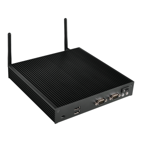
iBOX-155 2.2 Front View Description Kenshington Lock 2 x USB 2.0 Ports 2 x COM Ports HDD LED Power LED On-/off Switch Status LED Definitions Power LED Status Description Solid Green Power on Power off HDD Status LED Status Description HDD installed HDD uninstalled... -
Page 10: Rear View
2.3 Rear View No. Description No. Description Antenna Port VGA Port (VGA1) DC Jack (DC IN) HDMI Port (HDMI1) 2 x USB 3.0 Ports (USB3_0_1) Line out (Lime) 2 x USB 3.0 Ports (USB3_2_3) Microphone (Pink) LAN RJ-45 Port (LAN1)* Antenna Port LAN RJ-45 Port (LAN2)* * There are two LEDs on each LAN port. -
Page 11: Chapter 3 Hardware Installation
iBOX-155 Chapter 3 Hardware Installation This chapter provides step-by-step procedures on how to install components. Installation Procedures Removing the chassis top cover Installing the memory modules (SO-DIMM) Installing the 2.5-inch hard drive Installing the WiFi module and the WiFi antennas (Optional) Replacing the chassis top cover After making sure that you have properly connected the power supply and all the necessary peripherals, power on the system. -
Page 12: Removing The Chassis Bottom Cover
3.1 Removing the Chassis Top Cover 1. Remove the three screws on the front panel. 2. Remove the three screws on the rear panel. 3. Lift up and remove the top cover. -
Page 13: Installing Memory Modules (So-Dimm)
iBOX-155 3.2 Installing Memory Modules (SO-DIMM) This motherboard provides two 204-pin DDR3 (Double Data Rate 3) SO-DIMM slots. Please install the SO-DIMM module into the DDR3_A2 for the first priority. It is not allowed to install a DDR or DDR2 memory module into a DDR3 slot; otherwise, this motherboard and SO-DIMM may be damaged. -
Page 14: Installing The 2.5-Inch Hard Drive
3.3 Installing the 2.5-inch Hard Drive 1. Release the two screws on the front panel and the two screws in the chassis to remove the hard drive bracket. 2. Place a HDD into the bracket with the printed circuit board side facing down. Carefully align the mounting holes in the hard drive and the bracket. - Page 15 iBOX-155 4. Attach one end of the SATA 1 to 1 Power Cable to the hard drive. 5. Place the bracket into the chassis. Carefully align the mounting holes on the bracket and the chassis. 6. Secure the bracket to the chassis using the four screws 7.
-
Page 16: Installing The Wifi Module And The Wifi Antennas (Optional)
3.4 Installing the WiFi module and the WiFi antennas (Optional) 1. Based on the length of the WiFi Module Card, release and move the standoff by hand to the nut to be used . 2. Insert the WiFi Module Card into the mini PCI Express slot (MINI_PCIE1). 3. - Page 17 iBOX-155 5. Connect the two WiFi 2.4/5 GHz Antennas to the antenna connectors on the rear panel. Turn the antenna clockwise until it is securely connected. 6. Set the WiFi 2.4/5 GHz Antenna at 90-degree angle. *You may need to adjust the direction of the antenna for a stronger signal.
-
Page 18: Replacing The Chassis Bottom Cover
3.5 Replacing the Chassis Top Cover 1. Replace the top cover. 2. Secure the three screws on the front panel. 3. Secure the three screws on the rear panel. -
Page 19: Chapter 4 Motherboard
iBOX-155 Chapter 4 Motherboard 4.1 Motherboard Layout DC_JACK1 TO_UPS1 SATA_1 SATA_PWR1 FROM_UPS1 USB 3.0 T: USB1 B: USB0 USB3_PWR1 USB 3.0 USB3_PWR2 BIOS T: USB3 Chip B: USB2 LAN1 LAN2 USB2H_0_1 USB_PWR_H1 CPU_FAN1 USB_PWR_H2 USB2H_2_3 DDR3_B1 (Support DDR3L Only) VGA_H1 PANEL1 DDR3_A1 (Support DDR3L Only) HDMI1... - Page 20 No. Description 2-pin UPS Module Power Input Connector ATX Power Connector (Input 12V-24V) SATA Power Output Connector SATA3 Connector (SATA_1) LVDS Panel Connector BLT_PWM1 Backlight Volume Control (BLT_VOL1) Backlight Power Connector (BLT_PWR1) Backlight Power Select (LCD_BLT_VCC) (BKT_PWR1) Panel Power Selection (LCD_VCC) (PNL_PWR1) 4-Pin CPU FAN Connector (+12V) System Panel Header Printer Port / GPIO Header (LPT_GPIO1)
-
Page 21: Motherboard Specifications
iBOX-155 4.2 Motherboard Specifications Form Dimensions Mini-ITX (6.7-in x 6.7-in) Factor ® Intel Pentium/Celeron Braswell SoC Supports Hyper-Threading Technology Default N3150 Quad core 6W processor Core Processor (By CPU, Max 4) Number System Max Speed (By CPU) L2 Cache (By CPU) Chipset (By CPU) BIOS... - Page 22 AT/ATX Supported Requirements -AT : Directly PWR on as power input ready Power On -ATX : Press button to PWR on after power input ready Environment Temperature 0ºC – 60ºC * For detailed product information, please visit our website: http://www.asrock.com...
-
Page 23: Jumpers Setup
iBOX-155 4.3 Jumpers Setup The illustration shows how jumpers are setup. When the jumper cap is placed on the pins, the jumper is “Short”. If no jumper cap is placed on the pins, the jumper is “Open”. The illustration shows a 3-pin jumper whose pin1 and pin2 are “Short” when a jumper cap is placed on these 2 pins. - Page 24 Panel Power Use this to set up the VDD Selection (LCD_ power of the LVDS connector. VCC) 1-2: +3V (5-pin PNL_PWR1) 2-3: +5V (see p.15, No. 10) 3-4: +5V 4-5: +12V Backlight Power Selection Use this to set up the backlight (LCD_BLT_VCC) power of the LVDS connector (5-pin BKT_PWR1)
- Page 25 iBOX-155 USB2 Power Setting Jump- (for USB2H_0_1) 1-2: +5V (3-pin USB_PWR_H1) 2-3: +5VSB (see p.15, No. 28) (for USB2H_2_3) 1-2: +5V (3-pin USB_PWR_H2) 2-3: +5VSB (see p.15, No. 28) USB3 Power Setting Jumpers (for USB3_0_1) 1-2: +5V (3-pin USB3_PWR1) 2-3: +5VSB (see p.15, No.
-
Page 26: Onboard Headers And Connectors
4.4 Onboard Headers and Connectors Onboard headers and connectors are NOT jumpers. Do NOT place jumper caps over these headers and connectors. Placing jumper caps over the headers and connectors will cause permanent damage to the motherboard. SATA3 Connector This Serial ATA3 (SATA3) con- (SATA_1: see p.15, No. - Page 27 iBOX-155 3W Audio AMP Output Wa- Signal Name OUTLN (4-pin SPEAKER1) OUTLP (see p.15 No. 26) OUTRP OUTRN Front Panel Audio Header This is an interface for front PRESENCE# (9-pin HD_AUDIO1) panel audio cable that allows MIC_RET OUT_RET (see p.15 No. 25) convenient connection and control of audio devices.
- Page 28 CPU Fan Connector Please connect the CPU fan cable FAN_SPEED_CONTROL (4-pin CPU_FAN1) FAN_SPEED to the connector and match the +12V (see p.15 No. 11) black wire to the ground pin. Though this motherboard provides 4-Pin CPU fan (Quiet Fan) support, the 3-Pin CPU fan still can work successfully even without the fan speed control function.
- Page 29 iBOX-155 LVDS Connector Signal Name Signal Name (40-pin LVDS1) LCD_VCC LCD_VCC (see p.15 No. 5) LDDC_CLK +3.3V LVDS_A_DATA0# LDDC_DATA LVDS_A_DATA0 LVDS_A_DATA1 LVDS_A_DATA1# LVDS_A_DATA2# LVDS_A_DATA2 LVDS_A_DATA3 LVDS_A_DATA3# LVDS_A_CLK# LVDS_A_CLK LVDS_B_DATA0 LVDS_B_DATA0# LVDS_B_DATA1# LVDS_B_DATA1 LVDS_B_DATA2 LVDS_B_DATA2# LVDS_B_DATA3# DPLVDD_EN LVDS_B_DATA3 LVDS_B_CLK LVDS_B_CLK# CON_LBKLT_EN LCD_BLT_VCC CON_LBKLT_CTL LCD_BLT_VCC...
- Page 30 SATA Power Output Connector (4-pin SATA_PWR1) +12V (see p.15 No. 3) Buzzer Header (2-pin BUZZ1) SPKR (see p.15, No. 23) Chassis Intrusion Headers This motherboard (2-pin CI1, CI2) supportsCASE OPEN (see p.15, No. 18) detection feature that Signal detects if the chassis cover has been removed.
- Page 31 iBOX-155 COM4, 5, 6 Headers (RS232) (9-pin COM4/COM5/ COM6) (see p.15, No. 20) SIGNAL SIGNAL SIGNAL SIGNAL SIGNAL NAME NAME NAME NAME NAME DDCD# TTXD RRTS# +5V/+12V RRXD DDTR# DDSR# CCTS# LPC Header This connector supports Trusted (19-pin LPC1) Platform Module (TPM) system, (see p.15, No.
-
Page 32: Expansion Slots (Mini-Pcie And Mini-Pcie/Mini-Sata Slots)
4.5 Expansion Slots (mini-PCIe/mini-SATA Slots) There is 1 mini-PCIe slot and 1 mini-SATA slot on this motherboard. Before installing an expansion card, please make sure that the power supply is switched off or the power cord is unplugged. Please read the documentation of the expansion card and make necessary hardware settings for the card before you start the installation.
Need help?
Do you have a question about the iBOX-155B and is the answer not in the manual?
Questions and answers