Tripp Lite 12U Wall-Mounted SmartRack Enclosure SRW12US Owner's Manual
12u wall-mounted enclosure
Hide thumbs
Also See for 12U Wall-Mounted SmartRack Enclosure SRW12US:
- Specifications (3 pages) ,
- Owner's manual (32 pages) ,
- Overview (2 pages)
Table of Contents
Advertisement
Quick Links
SmartRack
Table of Contents
Owner's Manual
12U Wall-Mounted
Model: SRW12US
Tripp Lite World Headquarters
1111 W. 35th Street, Chicago, IL 60609 USA
(773) 869-1234 • www.tripplite.com
Copyright © 2009 Tripp Lite. All trademarks are the sole property of their respective owners.
™
Enclosure
2
2
3
4
4
4
4
5
5
Francais
5
5
5
6
6
6
6
7
7
7
8
8
8
9
Advertisement
Table of Contents

Related Manuals for Tripp Lite 12U Wall-Mounted SmartRack Enclosure SRW12US


Summary of Contents for Tripp Lite 12U Wall-Mounted SmartRack Enclosure SRW12US
- Page 1 5.2 Cable Access & Management 5.3 Reversing the Enclosure 5.4 Mounting Rails 5.5 Adjusting Mounting Rail Depth Copyright © 2009 Tripp Lite. All trademarks are the sole property of their respective owners. ™ Enclosure Model: SRW12US 6. Wall Mounting the Enclosure 6.1 Mounting...
-
Page 2: Overview
Do not reship the enclosure with additional equipment unless the enclosure was shipped with a special shock pallet (“SP1” models only). The combined weight of the enclosure and installed equipment must not exceed the load capacity of the pallet. Tripp Lite is not responsible for any damage that occurs during reshipment. -
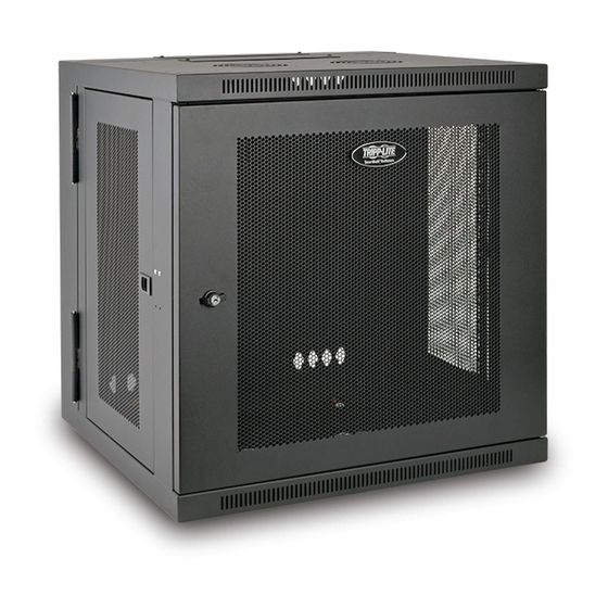
Page 3: Feature Identification
3. Feature Identification Rear Door Front Door Horizontal Rails Vertical Mounting Rails Removeable Cable Access Hole Covers Vents Locking/Removeable Side Panels... -
Page 4: Enclosure Installation
With one person on each side, carefully lift the enclosure out of the box and place on a firm, level surface. Examine the enclosure for any damage or loose parts. Confirm all parts are present. If anything is missing or damaged, contact Tripp Lite for assistance. Do not attempt to use the enclosure if it has been damaged. -
Page 5: Ground Connection
4. Enclosure Installation 4.4 Ground Connection All parts of the enclosure are grounded to the frame of the enclosure. Use the enclosure’s front or rear threaded grounding point and an M6 screw (included) to connect the frame of the enclosure directly to your facility’s earth ground connection with an 8 AWG (3.264 mm) wire. -
Page 6: Adjusting Mounting Rail Depth
5. Enclosure Configuration 5.4 Mounting Rails The enclosure comes with mounting rails that have square holes for mounting rack equipment. To install equipment, use the included cage nuts and other hardware. (See page 7 for installation of cage nuts.) Warning: Be sure to have the enclosure securely mounted to the wall, or in its final position on the floor before mounting any equipment inside. -
Page 7: Equipment Installation
Note: You may wish to use a cage nut tool (user-supplied) to aid cage nut installation and removal. 8. Optional Casters An optional caster accessory kit (Model: SRCASTER) is available separately through Tripp Lite. Go to www.tripplite.com or call (773) 869-1234 for details. The SRCASTER Kit consists of 4 casters with required locknuts and bolts for installation. -
Page 8: Warranty & Warranty Registration
Store the enclosure in its original shipping container if possible. Service The enclosure is covered by the limited warranty described in this manual. For more information, call Tripp Lite Customer Service at (773) 869-1234. 11. Warranty and Warranty Registration...
Need help?
Do you have a question about the 12U Wall-Mounted SmartRack Enclosure SRW12US and is the answer not in the manual?
Questions and answers