
Subscribe to Our Youtube Channel
Related Manuals for Dover PSG Wilden P200


Summary of Contents for Dover PSG Wilden P200
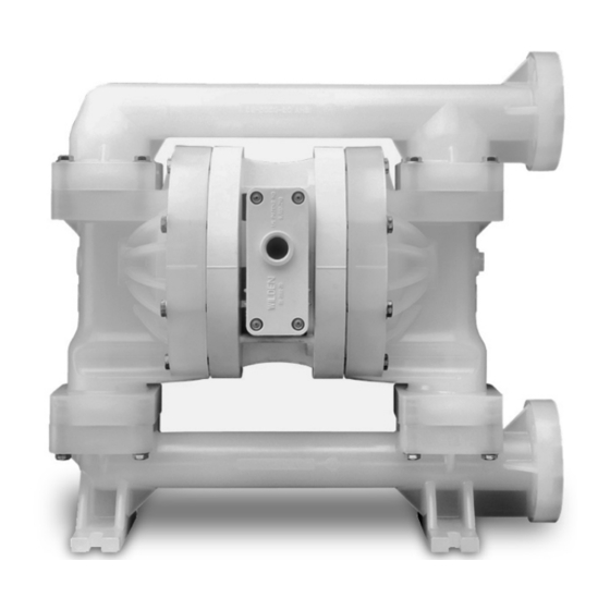
- Page 1 ENGINEERING OPERATION & MAINTENANCE MANUAL P200 Bolted Plastic Pump Where Innovation Flows WIL-11070-E-16...
- Page 2 No part of this document may be reproduced, stored in a retrieval system, or transmitted in any form or any means electronic or mechanical, including photocopying and recording, without the written permission of PSG, a Dover Company, except as described by the terms of those agreements.
-
Page 3: Table Of Contents
P200 Bolted Plastic CONTENTS SECTION 1: Precautions – Read First! ..................... 4 SECTION 2: Wilden Pump Designation System ..................5 SECTION 3: How It Works .......................... 6 SECTION 4: Dimensional Drawings ......................7 SECTION 5: Performance ........................... 9 P200 Plastic Rubber-Fitted ........................9 P200 Plastic TPE-Fitted .......................... -
Page 4: Section 1: Precautions - Read First
P200 Bolted Plastic SECTION 1 PRECAUTIONS – READ FIRST! WARNING: Always wear safety glasses when operating CAUTION: Thoroughly flush pumps before installing a pump to avoid eye injury. If diaphragm rupture occurs, them into process lines. Clean and/or sanitize FDA- and material being pumped may be forced out of the air USDA- approved pumps before using them. -
Page 5: Section 2: Wilden Pump Designation System
P200 Bolted Plastic SECTION 2 WILDEN PUMP DESIGNATION SYSTEM P200 PLASTIC LEGEND P 200 / / X X X / X X / X X / X X X X 25 mm (1") Pump O-RINGS MODEL VALVE SEATS SPECIALTY Maximum Flow Rate: VALVE BALLS CODE (if applicable) - Page 6 P200 Bolted Plastic SECTION 3 HOW IT WORKS – AIR-OPERATED DOUBLE-DIAPHRAGM PUMP The Wilden diaphragm pump is an air-operated, positive displacement, self-priming pump. These drawings show flow pattern through the pump upon its initial stroke. It is assumed the pump has no fluid in it prior to its initial stroke. FIGURE 1 The air valve directs pressurized air to FIGURE 2 When the pressurized diaphragm, FIGURE 3 At completion of the stroke, the air...
- Page 7 P200 Bolted Plastic SECTION 4 DIMENSIONAL DRAWING P200 Plastic – Polypropylene DIMENSIONS METRIC ITEM STANDARD (inch) (mm) 18.0 10.2 15.0 17.1 10.2 11.3 13.9 12.2 DIN FLANGE 85 DIA. 3.3 DIA. 115 DIA. 4.5 DIA. 15 DIA. 0.6 DIA. ANSI FLANGE 79 DIA.
- Page 8 P200 Bolted Plastic DIMENSIONAL DRAWING P200 Plastic - Polypropylene, Center Ported DIMENSIONS METRIC STANDARD ITEM (mm) (inch) 18.9 10.2 15.0 17.1 10.2 11.3 13.9 12.2 DIN FLANGE 85 DIA. 3.3 DIA. 115 DIA. 4.5 DIA. 14 DIA. 0.6 DIA. ANSI FLANGE 79 DIA.
-
Page 9: Section 5: Performance
P200 Bolted Plastic SECTION 5 PERFORMANCE P200 PLASTIC RUBBER-FITTED Ship Weights.……Polypropylene 10 kg (22 lb) PVDF 15 kg (32 lb) Air Inlet………………………..…….6 mm (1/4") Inlet…...…………………...…………25 mm (1") Outlet………………...………………25 mm (1") Suction Lift……………………3.6 m Dry (11.9’) 9.1 m Wet (30.0’) Disp. per Stroke ……..…..0.32 L (.086 gal) Max. -
Page 10: P200 Plastic Reduced-Stroke Ptfe-Fitted
P200 Bolted Plastic PERFORMANCE P200 PLASTIC REDUCED-STROKE PTFE-FITTED Ship Weights.……Polypropylene 10 kg (22 lb) PVDF 15 kg (32 lb) Air Inlet………………………..…….6 mm (1/4") Inlet…...…………………...…………25 mm (1") Outlet………………...………………25 mm (1") Suction Lift……………………..2.4 m Dry (7.9’) 9.4 m Wet (31.0’) Disp. per Stroke ……..…..0.22 L (.057 gal) Max. -
Page 11: Suction Lift Capability
P200 Bolted Plastic SECTION 5 SUCTION LIFT CAPABILITY P200 PLASTIC SUCTION LIFT CAPABILITY Suction-lift curves are calibrated for pumps operating at 305 m (1,000') above sea level. This chart is meant to be a guide only. There are many variables that can affect your pump's operating characteristics. -
Page 12: Section 6: Suggested Installation, Operation, Maintenance, And Troubleshooting
P200 Bolted Plastic SECTION 6 SUGGESTED INSTALLATION, OPERATION, MAINTENANCE AND TROUBLESHOOTING Wilden pumps are designed to meet the performance requirements of be eliminated. In addition, pump efficiency can be adversely even the most demanding pumping applications. They have been affected if proper attention is not given to site location. designed and manufactured to the highest standards and are ... - Page 13 P200 Bolted Plastic SUGGESTED INSTALLATION, OPERATION, MAINTENANCE AND TROUBLESHOOTING pump damage will not occur. The pump has reached a “deadhead” NOTE: In the event of a power failure, close the shut- situation and can be restarted by reducing the fluid discharge off valve if you do not want the pump to restart when the pressure or increasing the air inlet pressure.
-
Page 14: Section 7: Disassembly/Reassembly
P200 Bolted Plastic SUGGESTED INSTALLATION, OPERATION, MAINTENANCE AND TROUBLESHOOTING Troubleshooting Pump air valve freezes. Pump will not run or runs slowly. Check for excessive moisture in the compressed air. Remove plug from pilot spool exhaust. Either install a dryer or a hot air generator for compressed Ensure that the air inlet pressure is at least 0.4 bar (5 psig) air. -
Page 15: Pump Disassembly
P200 Bolted Plastic SECTION 7 DISASSEMBLY / REASSEMBLY PUMP DISASSEMBLY Tools Required: CAUTION: Before attempting any maintenance or repair, disconnect the compressed air line to the pump and allow all air pressure to bleed from the pump. Disconnect all 1/2"... - Page 16 P200 Bolted Plastic DISASSEMBLY / REASSEMBLY Step 4 Step 5 Step 6 Remove the discharge valve balls, seats Using a 13 mm (1/2") wrench, remove the Remove the inlet valve balls, seats and and valve seat O-rings from the discharge inlet manifold.
- Page 17 P200 Bolted Plastic DISASSEMBLY / REASSEMBLY Step 10 Step 11 Step 12 After loosening and removing the outer To remove the remaining diaphragm Inspect diaphragms, outer and inner piston the diaphragm assembly can be assembly from the shaft, secure shaft pistons for signs of wear.
-
Page 18: Air Valve Disassembly
P200 Bolted Plastic DISASSEMBLY / REASSEMBLY AIR VALVE DISASSEMBLY Tools Required: CAUTION: Before attempting any maintenance or repair, disconnect the compressed air line to the pump and allow all air pressure to bleed from the pump. Disconnect all 3/16” Allen Wrench intake, discharge, and air lines. - Page 19 P200 Bolted Plastic DISASSEMBLY / REASSEMBLY Step 4 Step 5 Step 6 Remove air valve end cap to expose air Remove air valve spool from air valve body Remove pilot spool sleeve retaining snap valve spool by simply lifting up on end cap by threading one air valve bolt into the end ring on both sides of center section with once air valve bolts are removed.
-
Page 20: Reassembly Hints And Tips
P200 Bolted Plastic DISASSEMBLY / REASSEMBLY REASSEMBLY HINTS AND TIPS Upon performing applicable maintenance to the air distribution system, Maximum Torque Specifications the pump can now be reassembled. Please refer to the disassembly instructions for photos and parts placement. Description Torque Pro-Flo Air Valve... -
Page 21: Shaft Seal Installation
P200 Bolted Plastic DISASSEMBLY / REASSEMBLY SHAFT SEAL INSTALLATION Pre-Installation Tools After all the old seals have been removed, the inside of the bushing The following tools can be used to aid in the installation of should be cleaned to ensure no debris is left that may cause premature the new seals: damage to the new seals. -
Page 22: Section 8: Exploded View And Parts List
P200 Bolted Plastic SECTION 8 EXPLODED VIEW AND PARTS LIST P200 PLASTIC LW0490 REV. B ALL CIRCLED PART IDENTIFIERS ARE INCLUDED IN REPAIR KITS WIL-11070-E-16... - Page 23 P200 Bolted Plastic EXPLODED VIEW AND PARTS LIST P200/PKPPP/…/ P200/ PKPPP/…/0502 P200/KKPPP/…/ P200/KKPPP/…/0502 Item Description Qty. Air Distribution Components Air Valve Assembly Pro-Flo 01-2010-20 ™1 End Cap 01-2332-20 O-Ring, (-126), End Cap (Ø1.362 x Ø.103) 01-2395-52 Gasket, Air Valve, Pro-Flo 01-2615-52 ™...
- Page 24 P200 Bolted Plastic SECTION 9 ELASTOMER OPTIONS P200 PLASTIC REDUCED FULL-STROKE REDUCED REDUCED FULL-STROKE FULL-STROKE STROKE VALVE DIAPHRAGMS STROKE STROKE IPD VALVE BALLS VALVE SEAT MANIFOLD MATERIAL DIAPHRAGMS BACK-UP BACK-UP SEATS DIAPHRAGMS DIAPHRAGMS DIAPHRAGMS O-RINGS (4) O-RINGS (4) DIAPHRAGMS (2) DIAPHRAGMS Polyurethane 02-1010-50...
- Page 25 P200 Bolted Plastic NOTES WIL-11070-E-16...
- Page 26 P200 Bolted Plastic NOTES WIL-11070-E-16...
- Page 27 P200 Bolted Plastic NOTES WIL-11070-E-16...
- Page 28 P: +1 (909) 422 -1730 psgdover.com Where Innovation Flows ® ® Copyright 2021 PSG , a Dover Company ® reserves the right to modify the information and illustrations contained in this document without prior notice. This is a non-contractual document. WIL-11070-E-16...
Need help?
Do you have a question about the PSG Wilden P200 and is the answer not in the manual?
Questions and answers