Table of Contents
Advertisement
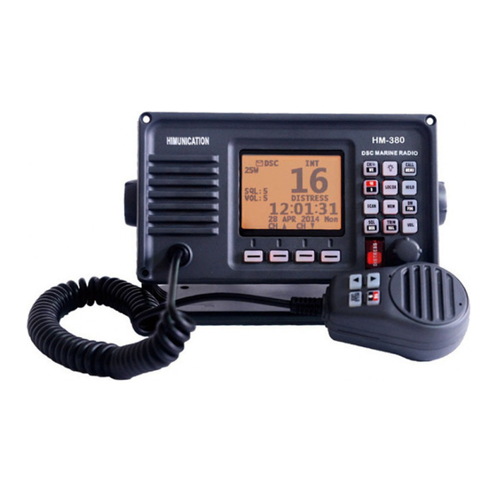
HM380 SeriesUser Manual
RF Radiation Information
RF Radiation Profile
Your radio is designed and tested to comply with a number of national and international standards and
guidelines (listed below) regarding human exposure to radio frequency electromagnetic energy. This
radio complies with the IEEE and ICNIRP exposure limits for occupational/controlled RF exposure
environment at operating duty factors of up to 50% transmitting .In terms of measuring RF energy for
compliance with the FCC exposure guidelines, your radio radiates measurable RF energy only while it is
transmitting (during talking in PTT mode), not when it is receiving (listening) or in standby mode.
The device complies with SAR and/or RF field strength limits of RSS-102 requirement
RF Radiation Safety
I
n order to ensure user health, experts from relevant industries including science, engineering, medicine
and health work with international organizations to develop standards for safe exposure to RF radiation.
These standards consist of:
United States Federal Communications Commission, Code of Federal Regulations; 47CFR part 2
sub-part J;
American National Standards Institute (ANSI)/Institute of Electrical and Electronic Engineers (IEEE) C95.
1-1992;
Institute of Electrical and Electronic Engineers (IEEE) C95. 1 – 1999;
International Commission on Non-Ionizing Radiation Protection (ICNIRP) 1998;
FCC Regulations
Federal Communication Commission (FCC) requires that all radio communication products should meet
the requirements set forth in the above standards before they can be marketed in the U.S, and the
manufacturer sHAIL post a RF label on the product to inform users of operational instructions, so as to
enhance their occupational health against exposure to RF energy.
Part 15 Compliance
This equipment has been tested and found to comply with the limits for a Class B digital device, pursuant
to part 15 of the FCC Rules. These limits are designed to provide reasonable protection against harmful
interference in a residential installation. This equipment generates uses and can radiate radio frequency
energy and, if not installed and used in accordance with the instructions, may cause harmful interference
to radio communications. However, there is no guarantee that interference will not occur in a particular
installation. If this equipment does cause harmful interference to radio or television reception, which can
be determined by turning the equipment off and on, the user is encouraged to try to correct the
interference by one or more of the following measures:
Reorient or relocate the receiving antenna.
I
ncrease the separation between the equipment and receiver.
Connect the equipment into an outlet on a circuit different from that to which the receiver
Consult the dealer or an experienced radio/TV technician for help. Note:"Changes or modifications to
is
connected.
— I—
Advertisement
Table of Contents

Related Manuals for Himunication HM380 Series


Summary of Contents for Himunication HM380 Series
- Page 1 HM380 SeriesUser Manual RF Radiation Information RF Radiation Profile Your radio is designed and tested to comply with a number of national and international standards and guidelines (listed below) regarding human exposure to radio frequency electromagnetic energy. This radio complies with the IEEE and ICNIRP exposure limits for occupational/controlled RF exposure environment at operating duty factors of up to 50% transmitting .In terms of measuring RF energy for compliance with the FCC exposure guidelines, your radio radiates measurable RF energy only while it is transmitting (during talking in PTT mode), not when it is receiving (listening) or in standby mode.
- Page 2 EU countries only. Warning- Limitations On Use This HM380 Series product contains simple chart, only as an aid to navigation for reference. Only Official Government Charts and Notice to Mariners contain all the current information needed for safe navigation.
-
Page 3: Table Of Contents
Contents 1 .Installation ..........................1 2. Front Panel/Back Panel/Wiring diagram................3 3.LCD Display ..........................6 4. Main Menu Operation on Screen ..................7 DSC Menu..........................7 MY MMSI ID setup ......................8 Individual Call/Position Request/Group Call/Test call ..........9 All Ship Call........................11 Receive Call Log......................12 Send Call Log ........................13 Phone Book ........................14 DSC Setup........................14 Main Menu ..........................15... - Page 4 The Local Time & Date on Screen: ..................28 NMEA 0183 and NMEA 2000 ....................29 Appendix B – Channel List ......................30 International Marine VHF Channels & Frequencies ..........30 U.S. Marine VHF Channels and Frequencies ..............32 Notes: ............................33 Specification...........................38 — —...
-
Page 5: Installation
1 .Installation The first installation solution 1.Place and fasten the mounting bracket on the console by 4 screws; 2. Mount the base station onto the bracket; 3. Attach the supplied mounting knobs from two sides of the bracket to fix the base station securely (as shown above). - Page 6 2 Use screwdriver respect ively t ight en t he screws on eit her side of the small mental bracket (as A screw of the below pict ure shown), make the small metal bracket fit tightly on the aluminum chassis 3 Similarly, use screwdriver respect ively t ight en t he screws on eit her side of t he small metal bracket (as B screw of the below pict ure shown), that will firmly against the inside of t he inst rument panel.
-
Page 7: Front Panel/Back Panel/Wiring Diagram
2. Front Panel/Back Panel/Wiring diagram Front Panel CH/*/WX—short press to enter private channel, long press to enter weather channel only available in US Back Light On/Off—short press to back light On/Off. Call/MENU—short press to enter “DSC Menu”, long press to enter “Main Menu”. 16/9—short press to enter channel 16 or press this button to quit all other modes and back to the priority channel quickly, long press will get second-priority channel 09 or any channel that you’ve set as second-priority channel. - Page 8 scan. MEM—short press to enter memory mode, long press to save/delete memory channel. DW/FOG—short press to enter Dual Watch Mode, long press to enter “Foghorn Menu”. SQL/MOB—short press to get SQL setting, long press to get MOB activated. TRIW/HAIL—short press to enter Tri Watch Mode, long press to enter “HAILER LISTEN MODE”...
- Page 9 Wiring diagram /HM380S/HM380C HM 380 RF antenna Power + Power - Hailer ext ernal speaker jack NM EA 0183 NM EA 2000( onl y f or HM380S/HM380C GND hole The details please check t he below table Ser i al Gener al Di f f er ent Col or Funct i on Descr i pt i on...
- Page 10 Power + +13. 8V r ed&bl ack power Power suppl y Power - Bl ack W hi t e HAI LER+ Bl ack Phone Jack Hai l er Bl ack HAI LER- AUDI O+ Bl ack 3. 5 m m Jack Ext er nal Speaker Bl ack USBRX...
-
Page 11: Lcd Display
3.LCD Display P-CH SQL:5 VOL:3 DISTRESS 12:07:38 02 MAY 2014 Fri 4. Main Menu Operation on Screen DSC Menu Short press the CALL/MENU key will be displayed as below on LCD: DSC Menu Individual Call Position Request All Ship Call Group Call Test Call Receive Call Log... - Page 12 — 7—...
-
Page 13: My Mmsi Id Setup
MY MMSI ID setup Firstly, long press CALL/MENU key to enter “Main Menu”. Secondly, select “ Operation” to enter “MY MMSI ID”. Then you can set up your related MMSI ID as below, generally you need to double confirm the MMSI ID. -
Page 14: Individual Call/Position Request/Group Call/Test Call
My MMSI ID Input MMSI 123------ EXIT My MMSI ID 123456789 EXIT Individual Call/Position Request/Group Call/Test call Press the “CALL/MENU” key and choose“Individual Call”, then choose “Input Address” or “From Phonebook”. Take individual call as example— Firstly you selected the “Input Address”, then input 9 digits manually such as 100000000 for your address as below: Input Address Input 9 digits... - Page 15 Individual Call Routine Exit Enter Next select the preferred channel such as 01 port operation and confirm to call Individual Call Select Channel: 01 port ops/vts 03 unauth orized 05 port ops/vts 06 inter ship 07 commercial 08 commercial Exit Enter Individual Call To: 100000000...
-
Page 16: All Ship Call
All Ship Call Select the All Ship item Menu Individual Call Position Request All Ship Call Group Call Test Call Receive Call Log Send Call log Phone Book Setup My MMSI ID Enter Exit All Ship Call Safety Urgency Exit Enter Safety Select Channel:... -
Page 17: Receive Call Log
All Ship Call To : All Ship Urgency Telephony by Channel 07 Exit Call SQL:5 COMMERCIAL Elapsed Exit The All Ship Call is sent. Receive Call Log When received DSC, you can check those messages from the “Distress Menu” and see the exact message. -
Page 18: Send Call Log
Receive call log Distress call Others call Exit Enter Received DSC Distress call Undesignated From: 123456789 GPS POS; Unknown 88: 88 UTC Exit Delete Send Call Log Press “CALL/MENU” key to choose “Send Call Log” item and see previous distress call, MOB call and other call that you have sent. -
Page 19: Phone Book
Send Call Log Distress Call MOB Call Others Call EXIT ENTER Phone Book Press “CALL/MENU” key to choose “Phone Book” item and can check the contacted ship by “Buddy List” and “Group List” DSC Menu Individual Call Position Request All Ship Call Group Call Test Call Receive Call Log... -
Page 20: Main Menu
DSC Menu Individual Call Position Request All Ship Call Group Call Test Call Receive Call Log Send Call Log Phone Book DSC Setup My MMSI ID EXIT ENTER DSC Setup Position Input Auto Ch Change Position Reply Test Ack EXIT ENTER Main Menu Long press the CALL/MENU key will display as below:... -
Page 21: Vhf Operation
VHF Operation Long press the CALL/MENU key to enter “VHF Operation” item as below for setup: Main Menu VHF Operation GPS Setup ATIS Operation Operation System config EXIT ENTER — 16—... - Page 22 VHF Operation Channel Band Set Priority 2nd Ch EXIT ENTER For VHF Operation, you can choose your preferred channel from below three options USA, INT and CAN. Channel Band Set Exit Enter For priority 2 Ch, you can select your preferred channel from below as your priority second channel.
-
Page 23: Gps Setup
GPS Setup Long press the CALL/MENU key to enter “GPS Setup” item for setup as below shown. Main Menu VHF Operation GPS Setup ATIS Operation Operation System config EXIT ENTER GPS Setup GPS Setting NMEA Output EXIT ENTER GPS Setting Ti me display Time offset COG/SOG Display... - Page 24 NMEA Output Enable Disable EXIT ENTER Follow like this, you can setup your priority as you wish. TCPA/ CPA Alarm enable Disable Enable Choose “Disable” or “Enable” item to enter disable or enable TCPA/ CPA alarm, then press ”ENTER” key to confirm. CPA (Closest point of approach)Alarm distance setup Input digits 03.0 NM...
-
Page 25: Atis Operation
ATIS Operation Long press the CALL/MENU key to enter “ATIS Operation” for setup. Main Menu VHF Operation GPS Setup ATIS Operation DSC Operation System config EXIT ENTER ATIS Operation My ATIS ID ATIS Function EXIT ENTER Choose to press for setup or more function as you wish. DSC Operation Long press the CALL/MENU key to enter “DSC Operation”... -
Page 26: System Config
Main Menu VHF Operation GPS Setup ATIS Operation Operation System config EXIT ENTER DSC Operation My MMSI ID DSC Function EXIT ENTER (My MMSI ID setup have been explained in previous chapter, please see Page**) System Config Long press the CALL/MENU key to enter “system config” for setup. Main Menu VHF Operation GPS Setup... -
Page 27: Distress Menu & Send The Distress Message
System Config Back Light Time LCD Contrast Key Beep Version Info Factory Reset Exit Enter Choose to press for setup or more function as you wish. Distress Menu & Send the Distress Message Pull the DISTRESS red cover and press the DISTRESS key. Then below “Distress Menu” will be displayed on LCD. - Page 28 SQL:5 DISTRESS Resend in 4:09 Pause Send Exit You can also choose to resend, pause or exit after this message was sent. From the ship info menu, you have three options: List mode, plotter mode, TCPA/CPA alarm list mode. If you choose option ‘ ship info list’ and press ‘enter’, you will open the list mode. NO.ERG RANGE MMIS 01/13 01 079°6825.77nm 566981045...
-
Page 29: Key Operation
If you choose option ’TCPA CPA Alarm List’ and press enter, you will open the TCPA/ CPA alarm list mode. NO.ERG RANGE MMIS 01/13 01 079°6825.77nm 566981045 02 079°6831.99nm 41347203 03 079°6831.98nm 41347206 04 079°6825.80nm 56698100 05 --------- 41397699 06 079°6825.32nm 40350600 Exit Enter From either mode, you can choose a target with UP/DOWN, then press enter to... -
Page 30: Special Function Of Distress Key & Real-Time Dsc
Special Function of DISTRESS key & Real-time DSC When sending distress message: Pull the Distress key cover and press the Red key into “Distress Menu” selection. Select current distress situation such as “Flooding”, then press and hold for 3 seconds, the selected DSC message will be send. -
Page 31: Dw/ Fog (Dual Watch/Foghorn)
DW/ FOG (Dual Watch/Foghorn) At the normal mode, short press “DW/FOG” key to activate the DUAL WATCH mode. Monitor the current channel and Ch 16 in cycle. Whenever weather alert is activated, the WX Alert channel will be monitored once every 4 seconds. Long press “DW/FOG”... -
Page 32: Up/Down Key
Up/Down Key At the normal mode, they act as Channel Up/Down key. When it presses > 0.5 sec, the channels will change in a quick way. It returns to normal mode when key press is released. LOC/DX short press to get conversion between local and distance mode (DX allows normal receive sensitivity;... -
Page 33: Other Features And Solutions
CH/*/WX Short press “CH/*/WX” key will trigger Private channel if there are private channels in EEPROM. Press “Up/Down” key will change private channel. Long press “CH/*/WX” key will enter WX mode in USA or CAN Band. Press “Up/Down” key to change WX channel. The “WX” icon will be displayed on the screen. Weather Alert Operation: (US Band only) At the weather mode, Long press the “CH/*/WX”... -
Page 34: The Local Time & Date On Screen
The Local Time & Date on Screen: UTC TI M E LOCAL TI M When HM380 cannot receive the GPS signal to display the current position, screen will automatic display the time and date. When radio received the GPS signal, screen will show the current GPS location, related UTC time and date will be shown below the GPS location mark. -
Page 35: Appendix B - Channel List
Appendix A List of Abbreviations Auxiliary Equipment Conducted Emissions Electromagnetic Compatibility European Norm Equipment Under Test Fast Transient Burst Marine Equipment Directive Quasi Peak Appendix B – Channel List International Marine VHF Channels & Frequencies CH No. XMIT Freq RCVFreq Single Freq Use 01 156.050 160.650... - Page 36 156.275 160.875 Public Correspondence, Port Operations and Ship Movement 66 156.325 160.925 Public Correspondence, Port Operations and Ship Movement 67 156.375 156.375 x Intership, Port Operations and Ship Movement 2 68 156.425 156.425 x Port Operations and Ship Movement 69 156.475 156.475 x Intership, Port Operations and Ship Movement 71 156.575...
-
Page 37: Marine Vhf Channels And Frequencies
radiated power does not exceed 1 Watt. 5. The use of Channels 75 and 76 should be restricted to navigation related communication only and all precautions should be taken to avoid harmful interference to channel 16. Transmit power is limited to 1 Watt. U.S. -
Page 38: Notes
61A 156.075 156.075 U.S. Government only 63A 156.175 156.175 Port Operations and Commercial, VTS. Available only in New Orleans / Lower Mississippi area. 64A 156.225 156.225 U.S. Coast Guard only 65A 156.275 156.275 Port Operations 66A 156.325 156.325 Port Operations 67 156.375 156.375 Commercial. - Page 39 6. Output power is initially set to 1 watt. User can temporarily override this restriction to transmit at high power. Canadian Marine VHF Channels and Frequencies CH No. XMIT Freq RCV Freq Area of Operation Use 156.050 160.650 PC Public Correspondence 156.100 160.700 PC Public Correspondence...
- Page 40 156.850 156.850 All areas Intership, Ship/Shore, Commercial, Non-commercial and Ship Movement: All operations limited to 1-watt maximum power. May also be used for on-board communications. 18A 156.900 156.900 All areas Intership, Ship/Shore and Commercial: Towing on the Pacific Coast. 19A 156.950 156.950 All areas except PC Intership and Ship/Shore: Canadian Coast Guard only.
- Page 41 and Ship Movement: Port operations only in the St.Lawrence River/Great Lakes Areas with 1-watt maximum power. 67 156.375 156.375 EC Intership, Ship/Shore and Commercial: Commercial fishing only. 67 156.375 156.375 All areas except EC Intership, Ship/Shore, Commercial, Non-commercial,Safety: May also be used for communications with aircraft engaged in coordinated search and rescue and antipollution operations.
- Page 42 83A 157.175 157.175 EC Intership and Ship/Shore: Canadian Coast Guard and other Government agencies. 161.775 AC, GL Safety: Continuous Marine Broadcast (CMB) Service. 157.225 161.825 PC Ship/Shore and Public Correspondence 157.275 161.875 AC, GL, NL Ship/Shore and Public Correspondence 157.325 161.925 PC Ship/Shore and Public Correspondence 157.375...
-
Page 43: Specification
Norway & Sweden 155.775 155.775 Fishing 155.825 155.825 Fishing --------------------------------------------------------------------------------------------------------------------------------------- Finland, Norway&Sweden 155.500 155.500 Leisure 155.525 155.525 Leisure 155.650 155.650 Leisure --------------------------------------------------------------------------------------------------------------------------------------- Netherlands 157.550 162.150 Marina 157.850 157.850 Leisure --------------------------------------------------------------------------------------------------------------------------------------- M1 157.850 157.850 Marina M2 161.425 161.425 Marina Specification ---VHF radio TX Frequency……………………………………………………………….156.025-157.425 MHz RX Frequency……………………………………………………………….
Need help?
Do you have a question about the HM380 Series and is the answer not in the manual?
Questions and answers