Sign In
Upload
Manuals
Brands
YZ Systems Manuals
Industrial Equipment
NJEX 7300G
YZ Systems NJEX 7300G Manuals
Manuals and User Guides for YZ Systems NJEX 7300G. We have
2
YZ Systems NJEX 7300G manuals available for free PDF download: Instructions & Operating Manual
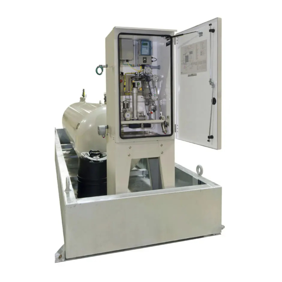
YZ Systems NJEX 7300G Instructions & Operating Manual (129 pages)
Natural gas odorization system
Brand:
YZ Systems
| Category:
Industrial Equipment
| Size: 12 MB
Table of Contents
Table of Contents
5
7300 G Table of Contents
11
Section 1: First Things to Know about the 7300G
11
How to Use this Manual
11
Typographic Conventions
11
Getting Help
11
Operation Specifications
12
Warranty
12
Theory of Operation
13
System Accessories
13
Section 2: System Installation
15
Standard System Components
15
System Flow Schematic
16
Standard System Mounting
17
Standard System Connections
18
Skid System Components
20
System Flow Schematic
22
Skid System Mounting
23
Skid System Connections
25
Section 3: Filling the Bulk Odorant Tank
27
Filling the Tank for the First Time
27
Refilling the Bulk Odorant Tank
28
Section 4: System Control & Electronics
29
Overview
29
To Use the Key Pad
29
To Power up the System
30
Test & Standby Keys
31
Battery & Solar Panel Assembly
32
LPS and Battery W/Cover Removed
32
Solar Panel
32
SPS and Battery W/Cover Removed
32
Communications Interface
33
Comm-Link Configuration
33
Section 5: Programming for Proportional-To-Flow Operation
35
Setting Operator Input Parameters
35
Odorant Injection Rate in Lbs/Mmcf (Mg/M3) of Gas
35
Pump Displacement in CC/Stroke
35
Odorant Density in Lbs/Gallon (G/CC) @ 60º F
35
Max Gas Flow in Mmcf/Hour (M3/Sec)
36
Low Flow Shutoff
36
Flow (no Signal) Input
36
Maximum Time/Stroke
37
The Odorant Output Setting
37
Odorant Tank
38
Expansion Tank Pressure Monitoring
38
Odorant Inlet Pressure Monitoring
39
Alarm to Relay Delay
40
Alarm to Call out Delay
40
MODBUS Address
40
MODBUS Parameters
41
Conclusion
41
Section 6: Programming for Proportional-To-Time Operation
43
Setting Operator Input Parameters
43
Pump Displacement in CC/Stroke
43
Odorant Density in Lbs/Gallon (G/CC.) @ 60ºF
43
Time Interval between Strokes of the Pump in XX.XX Minutes/Stroke
43
The Odorant Output Setting
44
Odorant Tank
44
Expansion Tank Pressure Monitoring
45
Odorant Inlet Pressure Monitoring
45
Alarm to Relay Delay
46
Alarm to Call out Delay
46
MODBUS Address
47
MODBUS Parameters
47
Conclusion
48
Section 7: Calibrating Signal Inputs
49
Analog Flow Input Calibration, 1-5 VDC / 4-20 Ma
49
Expansion Tank Pressure Transmitter Zero Calibration
51
Odorant Inlet Pressure Transmitter Zero Calibration
52
Pulse Flow Input Calibration, Dry Contact & Voltage Pulse
54
Calculation for Determining the Span Frequency Example
55
Section 8: Working with the N-300 System Displays
57
Display Functionality
57
To View Real Time Displays
58
Strokes Signaled
58
Odorant Injected
58
Pump Displacement
58
Pump Alarms
58
Meter Level - Verometer
59
Meter Alarms - Verometer
59
Meter Indicators, Non-Alarm
59
Expansion Tank
60
Odorant Inlet
60
Battery Voltage
60
Battery Alarm
60
Flow Input
60
Flow Input Alarms
60
Flow Input Indicators, Non-Alarm
60
Tank Level
61
Tank Level Alarm
61
Odorant Temperature
61
Section 9: Setting & Testing Alarms
63
Setting Alarm out Status
63
Testing Alarm out Status
65
Setting the Clock
68
Section 10: Mechanical System
71
Overview
71
Odorant Inlet Manifold & Bulk Odorant Filter Assembly
72
Fill Valve
72
Verometer
73
Model 7000F Pump
74
Odorant Discharge Manifold
74
NJEX Gas Filter
75
Solenoid Valve & Pneumatic Relay Manifold
76
Expansion Tank
76
Section 11: System Operation
77
Setting System Pressures and Valves
77
Low Pressure Relief Adjustment
77
Starting the System
78
To Stop the System
79
Section 12: System Maintenance
81
Annual Inspection
81
Bi-Annual Inspection
81
Recommended Spare Parts List
81
Preventative Maintenance Schedule
81
Recommended Maintenance Schedule
81
Weekly Inspection
81
Semi-Annual Inspection
81
Overflow Protector Assembly Inspection
82
Low Pressure Relief Adjustment
83
Conducting a Forward Purge
84
Venting Pressure Gas
86
Filling the Verometer
88
Priming & Starting the NJEX System
90
For Additional Help
93
How to Use this Section
93
Section 13: 7300G System Troubleshooting
93
Step-By-Step Resolution
93
Tank Level Alarms
93
Battery Alarm
94
Tank Level Alarm Troubleshooting Steps
94
Battery Alarm Troubleshooting Steps
94
Signal Alarms
95
Signal Non-Alarm Indicators
95
Loss of Flow Alarm Troubleshooting Steps
95
Overflow Alarm Troubleshooting Steps
95
Signal Alarm & Non-Alarm Indicator Troubleshooting Steps
95
Low Flow Non-Alarm Indicator Troubleshooting Steps
96
Overflow Non-Alarm Indicator Troubleshooting Steps
96
Verometer Alarms
96
Verometer Cable Alarm Troubleshooting Steps
97
Verometer No-Fill Alarm Troubleshooting Steps
97
Verometer Non-Alarm Indicators
97
Verometer Troubleshooting Steps
97
Verometer Leakage Alarm Troubleshooting Steps
98
Verometer Slow-Fill Alarm Troubleshooting Steps
98
Verometer Fill Valve Failure Alarm Troubleshooting Steps
99
Verometer Odorant Inlet Cable Alarm Troubleshooting Steps
99
Verometer Expansion Tank Cable Alarm Troubleshooting Steps
100
Verometer Expansion Tank Low Alarm Troubleshooting Steps
100
Verometer Odorant Inlet Hi Alarm Troubleshooting Steps
100
Verometer Odorant Inlet Low Alarm Troubleshooting Steps
100
Verometer Expansion Tank High Alarm Troubleshooting Steps
101
Verometer Fill Rate Non-Alarm Indicator Troubleshooting Steps
101
Verometer Overfill Non-Alarm Indicator Troubleshooting Steps
101
Pump Alarms
101
Pump over Pumping Alarm Troubleshooting Steps
102
Pump under Pumping Alarm Troubleshooting Steps
102
Section 13: 7300G System Troubleshooting Continued
101
Pump Failure Alarm Troubleshooting Steps
103
NJEX Model 7000F Pump Assembled
105
NJEX Model 7000F Pump Actuation Assembly, Exploded View
106
NJEX Model 7000F Pump, Diaphragm Cartridge, Exploded View
107
Fi
108
Appendix A: Illustrations
108
NJEX Model 7000F Pump Check Valve Assembly, Exploded View
108
Fill Valve, Exploded View
109
VM-1100 Verometer, with Filter Assembly Exploded View
110
Bulk Odorant Filter
111
NJEX Gas Filter
112
Electronics Assembly
113
SPS-12 Solar Power Supply Unit
114
LPS-120/240 Charger Supply Unit
115
Heater Wiring Diagram
116
Appendix B: N-300 Modbus Specifications
117
Boolean Registers
117
Communications Settings
117
Control Functions
117
N300 Modbus Function Support
117
Status Functions
118
Alarm Functions
119
Integer Registers
120
Result Data Functions
120
Exception Responses
122
Parameter Functions
122
Appendix C: Response Forms
123
For the Record Form
123
NJEX Trouble Shooting Form
124
Appendix D: Documents
125
Controller Display Diagram
125
Wiring Control Document
126
Appendix E: N-300 ATEX Connections
127
Advertisement
YZ Systems NJEX 7300G Instructions & Operating Manual (128 pages)
Brand:
YZ Systems
| Category:
Industrial Equipment
| Size: 12 MB
Table of Contents
Table of Contents
5
Section 1: First Things to Know about the NJEX
11
How to Use this Manual
11
Typographic Conventions
11
Getting Help
11
Operation Specifications
12
Warranty
12
Theory of Operation
13
System Accessories
13
Section 2: System Installation
15
Standard System Components
15
System Flow Schematic
16
Standard System Mounting
17
Standard System Connections
18
Skid System Components
20
System Flow Schematic
22
Skid System Mounting
23
Skid System Connections
25
Section 3: Filling the Bulk Odorant Tank
27
Filling the Tank for the First Time
27
Refilling the Bulk Odorant Tank
28
Section 4: System Control & Electronics
29
Overview
29
To Use the Key Pad
29
To Power up the System
30
Test & Standby Keys
31
Battery & Solar Panel Assembly
32
LPS and Battery W/Cover Removed
32
Solar Panel
32
SPS and Battery W/Cover Removed
32
Communications Interface
33
Comm-Link Configuration
33
Section 5: Programming for Proportional-To-Flow Operation
35
Setting Operator Input Parameters
35
Odorant Injection Rate in Mg/M3 of Gas
35
Pump Displacement in CC/Stroke
35
Odorant Density in G/CC @ 15.5ºC
35
Max Gas Flow in M3/Sec
36
Low Flow Shutoff
36
Flow (no Signal) Input
36
Maximum Time/Stroke
37
The Odorant Output Setting
37
Odorant Tank
38
Expansion Tank Pressure Monitoring
38
Odorant Inlet Pressure Monitoring
39
Alarm to Relay Delay
40
Alarm to Call out Delay
40
MODBUS Address
40
MODBUS Parameters
41
Conclusion
41
Section 6: Programming for Proportional-To-Time Operation
43
Setting Operator Input Parameters
43
Pump Displacement in CC/Stroke
43
Odorant Density in G/CC @ 15.5ºC
43
Time Interval between Strokes of the Pump in XX.XX Minutes/Stroke
43
The Odorant Output Setting
44
Odorant Tank
44
Expansion Tank Pressure Monitoring
45
Odorant Inlet Pressure Monitoring
45
Alarm to Relay Delay
46
Alarm to Call out Delay
46
MODBUS Address
47
MODBUS Parameters
47
Conclusion
48
Section 7: Calibrating Signal Inputs
49
Analog Flow Input Calibration, 1-5 VDC / 4-20 Ma
49
Expansion Tank Pressure Transmitter Zero Calibration
51
Odorant Inlet Pressure Transmitter Zero Calibration
52
Pulse Flow Input Calibration, Dry Contact & Voltage Pulse
54
Calculation for Determining the Span Frequency Example
55
Section 8: Working with the N-300 System Displays
57
Display Functionality
57
To View Real Time Displays
58
Strokes Signaled
58
Odorant Injected
58
Pump Displacement
58
Pump Alarms
58
Meter Level - Verometer
59
Meter Alarms - Verometer
59
Meter Indicators, Non-Alarm
59
Expansion Tank
60
Odorant Inlet
60
Battery Voltage
60
Battery Alarm
60
Flow Input
60
Flow Input Alarms
60
Flow Input Indicators, Non-Alarm
60
Tank Level
61
Tank Level Alarm
61
Odorant Temperature
61
Section 9: Setting & Testing Alarms
63
Setting Alarm out Status
63
Testing Alarm out Status
65
Setting the Clock
68
Section 10: Mechanical System
71
Overview
71
Odorant Inlet Manifold & Bulk Odorant Filter Assembly
72
Fill Valve
72
Verometer
73
Model Pump
74
Odorant Discharge Manifold
74
NJEX Gas Filter
75
Solenoid Valve & Pneumatic Relay Manifold
76
Expansion Tank
76
Section 11: System Operation
77
Setting System Pressures and Valves
77
Low Pressure Relief Adjustment
77
Starting the System
77
To Stop the System
79
Section 12: System Maintenance
81
Preventative Maintenance Schedule
81
Recommended Maintenance Schedule
81
Weekly Inspection
81
Semi-Annual Inspection
81
Annual Inspection
81
Bi-Annual Inspection
81
Recommended Spare Parts List
81
Overflow Protector Assembly Inspection
82
Low Pressure Relief Adjustment
83
Conducting a Forward Purge
84
Venting Pressure Gas
86
Filling the Verometer
88
Priming & Starting the NJEX System
90
Section 13: NJEX System Troubleshooting
93
How to Use this Section
93
For Additional Help
93
Step-By-Step Resolution
93
Tank Level Alarms
93
Tank Level Alarm Troubleshooting Steps
94
Battery Alarm
94
Battery Alarm Troubleshooting Steps
94
Signal Alarms
95
Signal Non-Alarm Indicators
95
Signal Alarm & Non-Alarm Indicator Troubleshooting Steps
95
Loss of Flow Alarm Troubleshooting Steps
95
Overflow Alarm Troubleshooting Steps
95
Low Flow Non-Alarm Indicator Troubleshooting Steps
96
Overflow Non-Alarm Indicator Troubleshooting Steps
96
Verometer Alarms
96
Verometer Non-Alarm Indicators
97
Verometer Troubleshooting Steps
97
Verometer Cable Alarm Troubleshooting Steps
97
Verometer No-Fill Alarm Troubleshooting Steps
97
Verometer Slow-Fill Alarm Troubleshooting Steps
98
Verometer Leakage Alarm Troubleshooting Steps
98
Verometer Fill Valve Failure Alarm Troubleshooting Steps
99
Verometer Odorant Inlet Cable Alarm Troubleshooting Steps
99
Verometer Odorant Inlet Low Alarm Troubleshooting Steps
100
Verometer Odorant Inlet Hi Alarm Troubleshooting Steps
100
Verometer Expansion Tank Cable Alarm Troubleshooting Steps
100
Verometer Expansion Tank Low Alarm Troubleshooting Steps
100
Verometer Expansion Tank High Alarm Troubleshooting Steps
101
Verometer Overfill Non-Alarm Indicator Troubleshooting Steps
101
Verometer Fill Rate Non-Alarm Indicator Troubleshooting Steps
101
Section 13: NJEX System Troubleshooting Continued
101
Pump Alarms
101
Pump over Pumping Alarm Troubleshooting Steps
102
Pump under Pumping Alarm Troubleshooting Steps
102
Pump Failure Alarm Troubleshooting Steps
103
NJEX Model 7300 Pump Assembled
105
NJEX Model 6300 Pump Assembled
106
NJEX Model 7300 Pump Actuation Assembly, Exploded View
107
Appendix A: Illustrations
108
NJEX Model 6300 Pump Actuation Assembly, Exploded View
108
NJEX Model 7300 Pump, Diaphragm Cartridge, Exploded View
109
NJEX Model 7300 Pump, Check Valve Assembly, Exploded View
110
NJEX Model 6300 Pump, Check Valve Assembly, Exploded View
111
Fill Valve, Exploded View
112
7300 Verometer, with Filter Assembly, Exploded View
113
Bulk Odorant Filter
115
NJEX Gas Filter
116
Electronics Assembly
117
Appendix B: N-300 Modbus Specifications
118
Communications Settings
118
N300 Modbus Function Support
118
Boolean Registers
118
Control Functions
118
Status Functions
119
Alarm Functions
120
Integer Registers
121
Result Data Functions
121
Parameter Functions
122
Exception Responses
123
Appendix C: Response Forms
124
For the Record Form
124
NJEX Trouble Shooting Form
125
Appendix D: Documents
126
Controller Display Diagram
126
Wiring Control Document
127
Advertisement
Related Products
YZ Systems NJEX 7300L
YZ Systems NJEX 610G
YZ Systems NJEX ZEO 6400
YZ Systems NJEX ZEO 7400
YZ Systems NJEX ZEO 8400
YZ Systems NJEX ZEO 9400
YZ Systems NJEX 8300G
YZ Systems NJEX 6300G
YZ Systems NJEX LVO 610G
YZ Systems NJEX LVO 610F
YZ Systems Categories
Industrial Equipment
Samplers
Measuring Instruments
Water Pump
Gateway
More YZ Systems Manuals
Login
Sign In
OR
Sign in with Facebook
Sign in with Google
Upload manual
Upload from disk
Upload from URL