Table of Contents
Advertisement
Quick Links
Service and Repair Manual
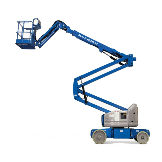
Z-40/23N
Z-40/23N RJ
Serial Number Range
from Z40N13-1902 to
Z40N16N-4499
from Z40NN-4500
This manual includes:
Repair procedures
Fault Codes
Electrical and
Hydraulic Schematics
For detailed maintenance
procedures, refer to the
appropriate Maintenance
Manual for your machine.
Part No. 1268528
Rev A2
September 2016
Advertisement
Table of Contents

Subscribe to Our Youtube Channel
Related Manuals for Terex Genie Z-40/23N


Summary of Contents for Terex Genie Z-40/23N
- Page 1 Service and Repair Manual Serial Number Range Z-40/23N from Z40N13-1902 to This manual includes: Z40N16N-4499 Repair procedures Fault Codes Z-40/23N RJ from Z40NN-4500 Electrical and Hydraulic Schematics For detailed maintenance procedures, refer to the appropriate Maintenance Manual for your machine. Part No.
-
Page 2: Find A Manual For This Model
Copyright © 2015 by Terex Corporation 1268528 Rev A, September 2016 First Edition, First Printing Genie is a registered trademark of Terex South Dakota, Inc. in the U.S.A. and many other countries. “Z” is a trademark of Terex South Dakota, Inc. - Page 3 September 2016 Service and Repair Manual Introduction Revision History Revision Date Section Procedure / Page / Description 9/2015 Release 3/2016 Specifications Updated Performance Specifications, Boom function speeds 3/2016 Repair Procedures Updated 1-1, How to Calibrate Joystick 3/2016 Repair Procedures Updated 9-1, How to Calibrate Steer angle sensor. 3/2016 Fault Codes Updated Control Systems Fault Codes Chart...
-
Page 4: Serial Number Legend
Service and Repair Manual September 2016 Introduction Serial Number Legend To August 31, 2016 1 Model 4 Sequence number 2 Model year 5 Serial number (stamped on chassis) 3 Facility code 6 Serial label (located under cover) From September 1, 2016 1 Model 4 Serial number (stamped on chassis) 2 Facility code... -
Page 5: Safety Rules
September 2016 Service and Repair Manual Safety Rules Section 1 Safety R ules Danger Failure to obey the instructions and safety rules in this manual and the appropriate Operator's Manual on your machine will result in death or serious injury. Many of the hazards identified in the operator's manual are also safety hazards when maintenance and repair procedures are performed. - Page 6 Service and Repair Manual September 2016 Safety Rules Personal Safety Workplace Safety Any person working on or around a machine must Any person working on or around a machine must be aware of all known safety hazards. Personal be aware of all known safety hazards. Personal safety and the continued safe operation of the safety and the continued safe operation of the machine should be your top priority.
-
Page 7: Table Of Contents
September 2016 Table of Contents Introduction Introduction ......................ii Important Information ..................... ii Find a Manual for this Model .................. ii Revision History..................... iii Serial Number Legend ..................iv Section 1 Safety Rules ......................v General Safety Rules ..................... v Section 2 Specifications ....................... - Page 8 September 2016 Table of Contents Platform Components ..................22 2-1 Platform Leveling Slave Cylinder ..............22 2-2 Platform Rotator ..................... 23 2-3 Platform Overload System ................24 2-4 Platform Recovery Overload ................26 Jib Boom Components ..................27 3-1 Jib Boom ......................27 3-2 Jib Boom Bell Crank (models without rotating jib boom) .......
- Page 9 September 2016 Table of Contents Manifolds ......................52 7-1 Function Manifold Components ..............52 7-2 Valve Adjustments - Function Manifold ............54 7-3 Jib Boom and Platform / Jib Boom Rotate Manifold Components ....58 7-4 Jib Boom and Platform / Jib Rotate Manifold Components ......59 7-5 Valve Coils .....................
- Page 10 September 2016 Table of Contents Section 5 Schematics ......................83 Introduction ......................83 Wire Circuit Legend ..................... 84 Wiring Coloring and Legend ................88 Power Cable Diagram ..................93 Motor Contoller Pin Legend ................. 94 Ground Control Box Pin Legend ................95 Platform Control Box Pin Legend.................
-
Page 11: Specifications
September 2016 Service and Repair Manual Specifications Section 2 Specific ati ons Machine Specifications Fluid capacities Hydraulic tank 8 gallons Tires and wheels Front Rear 30.3 liters Tire size 22 x 7 x 17.75 in 25.6 x 7 x 22 in Hydraulic system 10 gallons (solid rubber) -
Page 12: Performance Specifications
Service and Repair Manual September 2016 Specifications Performance Specifications Boom function speeds, maximum from platform controls (with rated load secured to platform) Z-40/23N and Z-40/23N RJ Jib boom up 16 to 20 seconds Jib boom down 16 to 20 seconds Drive speed, maximum Drive speed, stowed 4.5 mph... -
Page 13: Hydraulic Specification
September 2016 Service and Repair Manual Specifications Do not top off with incompatible Hydraulic Oil Specifications hydraulic fluids. Hydraulic fluids may be incompatible due to the Hydraulic Fluid Specifications differences in base additive Genie specifications require hydraulic oils which are chemistry. - Page 14 Service and Repair Manual September 2016 Specifications Chevron Rando HD Premium Oil Petro-Canada Environ MV 46 MV Fluid Properties Fluid Properties ISO Grade ISO Grade Viscosity index Viscosity index Kinematic Viscosity Kinematic Viscosity cSt @ 200°F / 100°C cSt @ 200°F / 100°C cSt @ 104°F / 40°C 33.5 cSt @ 104°F / 40°C...
-
Page 15: Hydraulic Component Specifications
September 2016 Service and Repair Manual Specifications Hydraulic Component Manifold Component Specifications Specifications Function pump Plug torque Type: Fixed displacement gear pump SAE No. 2 36 in-lbs / 4 Nm Displacement 0.244 cu in SAE No. 4 10 ft-lbs / 13 Nm 4 cc SAE No. -
Page 16: Machine Torque Specifications
Service and Repair Manual September 2016 Specifications Machine Torque Specifications Platform rotator 3/4 -10 center bolt, GR 8 (dry) 380 ft-lbs 515 Nm 3/4 - 10 center bolt, GR 8 (lubricated) 280 ft-lbs 379 Nm 3/8 -16 bolts, GR 8, (dry) 44 ft-lbs 60 Nm 3/8 -16 bolts, GR 8, (lubricated) -
Page 17: Hydraulic Hose And Fitting Torque Specifications
September 2016 Service and Repair Manual Specifications SAE O-ring Boss Port Hydraulic Hose and Fitting (tube fitting - installed into Aluminum) Torque Specifications (all types) Your machine is equipped with Parker Seal-Lok™ SAE Dash Size Torque ORFS or 37° JIC fittings and hose ends. Genie 14 ft-lbs / 19 Nm specifications require that fittings and hose ends be torqued to specification when they are removed... -
Page 18: Torque Procedure
Service and Repair Manual September 2016 Specifications JIC 37° fittings Torque Procedure Align the tube flare (hex nut) against the nose of the fitting body (body hex fitting) and tighten Seal-Lok™ fittings the hex nut to the body hex fitting to hand tight, Replace the O-ring. - Page 19 September 2016 Service and Repair Manual Specifications Working clockwise on the body hex fitting, make a second mark with a permanent ink marker to indicate the proper tightening position. Refer to Illustration 2. Note: Use the JIC 37° Fitting table in this section to determine the correct number of flats, for the proper tightening position.
-
Page 20: Sae And Metric Fasteners Torque Charts
Service and Repair Manual September 2016 Specifications Z-40/23N, Z-40/23N RJ Part No. 1268528... -
Page 21: Repair Procedures
September 2016 Service and Repair Manual Repair Procedures Section 3 Repair Pr oc edures Machine Configuration: Unless otherwise specified, perform each repair procedure with the machine in the following configuration: • Machine parked on a firm, level surface • Key switch in the off position with the key Observe and Obey: removed ... - Page 22 Service and Repair Manual September 2016 Repair Procedures About This Section Most of the procedures in this section should only be performed by trained service professional in a suitably equipped workshop. Select the appropriate repair procedure after troubleshooting the problem. Perform disassembly procedures to the point where repairs can be completed.
-
Page 23: Platform Controls
September 2016 Service and Repair Manual Platform Controls Move the joystick full stroke and hold for 5 seconds in each direction. Joysticks Result: The alarm should sound a short beep indicating successful joystick calibration in How to Calibrate a Joystick each direction. -
Page 24: How To Adjust The Joystick Threshold Setting
Service and Repair Manual September 2016 Platform Controls How to Adj ust the Joystick Thr es hol d Setting How to Adjust the Joystick Toggle switch controlled functions: Threshold Setting Note: Begin this procedure with the rotary speed control at the plaform controls turned fully in the The threshold setting of a joystick is the minimum counterclockwise direction. -
Page 25: How To Adjust The Maximum Speed Setting
September 2016 Service and Repair Manual Platform Controls How to Adj ust the Maxim um Speed Setti ng How to Adjust the Maximum When the display leaves SYSTEM READY mode, release the drive enable toggle switch Speed Setting and the steer rocker switch. The maximum speed setting of a joystick and Result: The display will show FAULTS. - Page 26 Service and Repair Manual September 2016 Platform Controls 13 Release the footswitch. Momentarily activate Low flow functions: the steer rocker in the left direction to 19 Momentarily activate one of the low flow decrease the value shown on the display in functions full stroke.
-
Page 27: How To Adjust The Function Ramp Up Time Setting
September 2016 Service and Repair Manual Platform Controls How to Adj ust the Functi on R amp U p Time Setti ng How to Adjust the Function Ramp Momentarily activate the steer rocker switch in the right direction until RAMP UP TIME is Up Time Setting shown on the display. - Page 28 Service and Repair Manual September 2016 Platform Controls 14 To adjust the ramp up time setting, release the To exit programming mode: foot switch. Momentarily move the steer 17 Move and hold the drive enable toggle switch rocker switch in the right direction to increase in the left direction until the display screen or momentarily in the left direction to returns to SYSTEM READY.
-
Page 29: How To Adjust The Function Ramp Down Time Setting
September 2016 Service and Repair Manual Platform Controls How to Adj ust the Functi on R amp D ow n Tim e Setting How to Adjust the Function Ramp Momentarily activate the steer rocker switch in the right direction until RAMP DOWN TIME is Down Time Setting shown on the display. -
Page 30: How To Adjust The Max Speed Drive Settings
Service and Repair Manual September 2016 Platform Controls How to Adj ust the Max Speed Driv e Settings 15 When ramp time has been achieved, activate How to Adjust the Max Speed the drive enable toggle switch to the right to Drive Settings save your changes. - Page 31 September 2016 Service and Repair Manual Platform Controls Using the rocker switch on the drive joystick, 16 Bring the machine to maximum drive speed momentarily activate steer left, left, right, and before reaching the start line. Begin timing left. when your reference point on the machine crosses the start line.
-
Page 32: Platform Components
Service and Repair Manual September 2016 Platform Components Tag, disconnect and plug the hydraulic hoses from the slave cylinder at the unions and Platform Leveling Slave Cylinder connect them together using a connector. The slave cylinder and the rotator pivot are the two Bodily injury hazard. -
Page 33: Platform Rotator
September 2016 Service and Repair Manual Platform Components How to Bleed the Slave Cylinder Platform Rotator Raise the primary boom to a horizontal position. Move the platform level toggle switch up and How to Bleed the Platform down through two platform leveling cycles to Rotator remove any air that might be in the system. -
Page 34: Platform Overload System
Service and Repair Manual September 2016 Platform Components Open the bottom bleed screw on the rotator, but do not remove it. Platform Overload System Bodily injury hazard. Spraying hydraulic oil can penetrate and How to Calibrate the Platform burn skin. Loosen hydraulic connections very slowly to allow Overload System the oil pressure to dissipate... - Page 35 September 2016 Service and Repair Manual Platform Components Determine the limit switch trigger point: Confirm the setting: Gently move the platform up and down by Turn the key switch to platform control. hand, so it bounces approximately 1 to Lift the test weight off the platform floor using a 2 inches / 2.5 to 5 cm.
-
Page 36: Platform Recovery Overload
Service and Repair Manual September 2016 Platform Components When the display leaves SYSTEM READY mode, release the drive enable toggle switch Platform Overload Recovery and the steer rocker switch. Message (software 1256908A and Result: The display will show FAULTS. later) Momentarily activate the drive enable toggle switch in the right direction. -
Page 37: Jib Boom Components
September 2016 Service and Repair Manual Jib Boom Components Remove the pin retaining fasteners from the jib boom leveling arm pivot pin at the platform Jib Boom rotator. Use a soft metal drift to remove the leveling How to Remove the Jib Boom arm pivot pin. -
Page 38: Jib Boom Bell Crank (Models Without Rotating Jib Boom)
Service and Repair Manual September 2016 Jib Boom Components 13 Remove the mounting fasteners from the jib boom/platform rotate manifold and lay the Jib Boom Bell Crank (models manifold to the side. Do not remove the hoses without rotating jib boom) or disconnect the wiring. -
Page 39: Jib Boom Rotator (Models With Rotating Jib Boom)
September 2016 Service and Repair Manual Jib Boom Components Support and secure the jib boom bell crank to an appropriate lifting device. Jib Boom Rotator (models with Remove the pin retaining fasteners from the rotating jib boom) slave cylinder rod-end pivot pin. Do not remove the pin. -
Page 40: How To Bleed The Jib Boom Rotator
Service and Repair Manual September 2016 Jib Boom Components How to Bleed the Jib Boom Rotator How to Bleed the Jib Boom Move and hold the function enable switch to either side and move and hold the jib boom Rotator rotate toggle switch to the left for approximately 5 seconds, then release it. -
Page 41: Jib Boom Lift Cylinder
September 2016 Service and Repair Manual Jib Boom Components Use a soft metal drift to tap the rod-end pivot pin half way out and lower one of the leveling Jib Boom Lift Cylinder links to the ground. Tap the pin the other direction and lower the opposite leveling link. -
Page 42: Primary Boom Components
Service and Repair Manual September 2016 Primary Boom Components Tag, disconnect and plug the hydraulic hoses from ports P and T at the jib boom/platform Cable Track rotate manifold. Cap the fittings on the manifold. The primary boom cable track guides the cables and hoses running up the boom. - Page 43 September 2016 Service and Repair Manual Primary Boom Components 11 Tag, disconnect and plug the jib 15 Place blocks between the cable track tube and boom/platform rotator hydraulic hoses at the the lower cable track. Secure the cable track union located above the primary boom lift tube and lower cable track together.
-
Page 44: How To Repair The Primary Boom Cable Track
Service and Repair Manual September 2016 Primary Boom Components How to R epair the Primary Boom C abl e Tr ack How to Repair the Primary Boom How to Shim the Primary Boom Cable Track Extend the boom until the wear pads are accessible. -
Page 45: How To Remove The Primary Boom
September 2016 Service and Repair Manual Primary Boom Components How to R emove the Primary Boom How to Remove the Primary Remove the cable track. Refer to Repair Procedure, How to Remove the Cable Track. Boom Remove the hose and cable guard from the Bodily injury hazard. - Page 46 Service and Repair Manual September 2016 Primary Boom Components Remove the primary boom drive speed limit 16 Place support blocks under the primary boom switch mounting fasteners and move the limit lift cylinder. switch out of the way. Do not disconnect the 17 Remove the pin retaining fasteners from the wiring.
-
Page 47: How To Disassemble The Primary Boom
September 2016 Service and Repair Manual Primary Boom Components How to Dis ass embl e the Primary Boom 22 Place 2 x 4 x 18 inch / 5 x 10 x 46 cm support How to Disassemble the Primary blocks under the cylinder, across the Boom secondary boom. -
Page 48: Primary Boom Lift Cylinder
Service and Repair Manual September 2016 Primary Boom Components Support and slide the extension tube and extension cylinder assembly out of the boom Primary Boom Lift Cylinder tube. The primary boom lift cylinder raises and lowers Crushing hazard. The boom the primary boom. - Page 49 September 2016 Service and Repair Manual Primary Boom Components 10 Remove the primary boom lift cylinder Support both ends of the primary boom lift barrelend pivot pin retaining fasteners. Use a cylinder with a second overhead crane or slide hammer to remove the barrel-end pivot similar lifting device.
-
Page 50: Primary Boom Extension Cylinder
Service and Repair Manual September 2016 Primary Boom Components Remove the hose and cable guard from the upper pivot. Primary Boom Extension Tag, disconnect and plug the primary boom Cylinder extension cylinder hydraulic hoses. Cap the fittings on the cylinder. The primary boom extension cylinder extends and retracts the primary boom extension tube. -
Page 51: Platform Leveling Master Cylinder
September 2016 Service and Repair Manual Primary Boom Components 12 Support and slide the extension cylinder out of the upper pivot. Platform Leveling Master Crushing hazard. The extension Cylinder cylinder could fall when removed from the extension boom if not The platform leveling master cylinder acts as a properly supported. - Page 52 Service and Repair Manual September 2016 Primary Boom Components Tag, disconnect and plug the master cylinder hydraulic hoses. Cap the fittings on the cylinder. Bodily injury hazard. Spraying hydraulic oil can penetrate and burn skin. Loosen hydraulic connections very slowly to allow the oil pressure to dissipate gradually.
-
Page 53: Secondary Boom Components
September 2016 Service and Repair Manual Secondary Boom Components 6 lower compression arm Secondary Boom components 1 upper pivot 7 turntable pivot 2 upper compression arm 8 counterweight (Z-30N / Z-30N RJ) 3 mid-pivot 9 upper secondary boom 4 compression link 5 lower secondary boom Part No. -
Page 54: Secondary Boom
Service and Repair Manual September 2016 Secondary Boom Components Tag, disconnect and plug the hydraulic hoses at the primary boom lift cylinder. Cap the Secondary Boom fittings on the cylinder. Bodily injury hazard. Spraying How to Disassemble the hydraulic oil can penetrate and burn skin. - Page 55 September 2016 Service and Repair Manual Secondary Boom Components 10 Attach a strap from an overhead crane to the 18 Use a soft metal drift to drive both pins out. lug on the rod end of one of the secondary 19 Remove the number 1 arm from the machine.
- Page 56 Service and Repair Manual September 2016 Secondary Boom Components 25 Pull all of the hoses and cables out of the 34 Use a soft metal drift to drive each pin out. upper pivot and out through the mid-pivot. Lay Remove the mid-pivot from the secondary the hoses and cables on the ground.
- Page 57 September 2016 Service and Repair Manual Secondary Boom Components 40 Remove the number 2 arm from the machine. 45 Attach the lifting strap from the overhead crane to the centerpoint of the number 3 arm Crushing hazard. The number for support. Do not apply any lifting pressure. 2 arm could become 46 Remove the pin retaining fasteners from the unbalanced and fall when...
-
Page 58: Secondary Boom Lift Cylinders
Service and Repair Manual September 2016 Secondary Boom Components Tag, disconnect and plug the hydraulic hoses on the secondary boom lift cylinder. Cap the Secondary Boom Lift Cylinder fittings on the cylinder. The secondary boom lift cylinder raises and lowers Bodily injury hazard. -
Page 59: Hydraulic Pump
September 2016 Service and Repair Manual Hydraulic Pump Tag, disconnect and plug the hydraulic hoses from the auxiliary pump. Cap the fittings on the How to Remove the Auxiliary pump. Pump Bodily injury hazard. Spraying hydraulic oil can penetrate and burn skin. -
Page 60: How To Remove The Function Pump
Service and Repair Manual September 2016 Hydraulic Pump How to Calibrate the Function Pump How to Remove the Function Pump Calibration of the function pump is essential to good machine performance and service life. The function pump motor operates at various Continued use of an uncalibrated or improperly speeds, depending on the flow and pressure calibrated function pump could result in reduced... - Page 61 September 2016 Service and Repair Manual Hydraulic Pump When the display leaves SYSTEM READY 12 Press down on the foot switch. Move and hold mode, release the drive enable toggle switch the primary boom rocker switch in the extend and the steer rocker switch. direction until the boom is fully extended and an audible alarm has sounded.
-
Page 62: Manifolds
Service and Repair Manual September 2016 Manifolds 7-1 Function Manifold Components The function manifold is located behind the ground controls turntable cover. Index Schematic Description Function Torque Item — Coil nut 4-5 ft-lbs / 5-7 Nm Proportional solenoid valve, Primary boom extend/retract 16-20 ft-lbs / 24-27 3 position 4 way Orifice, 0.046 inch / 1.17 mm... - Page 63 September 2016 Service and Repair Manual Manifolds Part No. 1268528 Z-40/23N, Z-40/23N RJ...
-
Page 64: Valve Adjustments - Function Manifold
Service and Repair Manual September 2016 Manifolds Note: The function enable toggle switch must be 7-2 Valve Adjustments - Function activated within 2 seconds of the audible tone. Manifold Result: The green LED on the TCON should change from a slow blinking light to a rapid How to Calibrate the Proprotional blinking light. - Page 65 September 2016 Service and Repair Manual Manifolds Move and hold the secondary boom toggle Move and hold the jib boom toggle switch in switch in the down direction. the up direction. Momentarily activate the platform level toggle switch in the up direction Result: The pressure gauge shows 1100 psi to increase the relief pressure or in the down /76 bar.
- Page 66 Service and Repair Manual September 2016 Manifolds How to Adjust the Secondary Adjust the internal hex socket. Turn it clockwise to increase the pressure or Boom Down Relief Valve counterclockwise to decrease the pressure. Install the relief valve cap. Turn the machine off. Locate the proportional relief valve (item BW) on the function manifold.
- Page 67 September 2016 Service and Repair Manual Manifolds How to Adjust the Platform Level Adjust the internal hex socket. Turn it clockwise to increase the pressure or Relief Valve counterclockwise to decrease the pressure. Install the relief valve cap. Turn the machine off. Locate the proportional relief valve (item BW) on the function manifold.
-
Page 68: Jib Boom And Platform / Jib Boom Rotate Manifold Components
Service and Repair Manual September 2016 Manifolds Jib Boom / Platform Rotate Manifold Components, Z-40/23N The jib boom/platform rotate manifold is mounted to the jib boom. Index Schematic Description Function Torque Item — Coil nut 4-5 ft-lbs / 5-7 Nm Proportional solenoid valve, Jib boom up / down 18-20 ft-lbs / 25-27 Nm... -
Page 69: Jib Boom And Platform / Jib Rotate Manifold Components
September 2016 Service and Repair Manual Manifolds Jib Boom and Platform / Jib Rotate Manifold Components, Z-40/23N The jib boom/platform rotate manifold is mounted to the jib boom. Index Schematic Description Function Torque Item — Coil nut 4-5 ft-lbs / 5-7 Nm Proportional solenoid valve, Jib boom up/down 18-20 ft-lbs / 25-27 Nm... -
Page 70: Valve Coils
Service and Repair Manual September 2016 Manifolds Test the coil resistance using a multimeter set to resistance (Ω). Refer to the Valve Coil Valve Coils Resistance Specification table. Result: If the resistance is not within the How to Test a Coil adjusted specification, plus or minus 10%, replace the coil. -
Page 71: Turntable Rotation Components
September 2016 Service and Repair Manual Turntable Rotation Components Disconnect the battery packs from the machine. Turntable Rotation Assembly Electrocution/burn hazard. Contact with electrically charged circuits could result in death or How to Remove the Turntable serious injury. Remove all rings, Rotation Assembly watches and other jewelry. -
Page 72: Steer Axle Components
Service and Repair Manual September 2016 Steer Axle Components Install the new steer sensor assembly to the 9-1 Steer Angle Sensor yoke pivot pin. Loosely install the cover retaining fasteners. How to Replace the Steer Angle Note: Be sure the sensor activator pin is engaged Sensor into the sensor. -
Page 73: How To Calibrate The Steer Angle Sensor
September 2016 Service and Repair Manual Steer Axle Components 11 Momentarily activate the drive enable toggle How to Calibrate the Steer Angle switch in the right direction. Sensor Result: The display will show YES. Proceed to Turn the key switch to platform control. step 12. - Page 74 Service and Repair Manual September 2016 Steer Axle Components Result: The display will show NO and ENABLE will appear at the bottom of the screen. 19 Adjust the steer wheels fully in the left direction 20 Momentarily activate the drive enable toggle switch in the right direction.
-
Page 75: Non-Steer Axle Components
September 2016 Service and Repair Manual Non-steer Axle Components Tag and disconnect the power cables from the 10-1 drive motor. Drive Motors Tag and disconnect the electrical connectors for the brake, speed and temperature sensors How to Remove a Drive Motor at the drive motor. -
Page 76: 10-2 Drive Brake
Service and Repair Manual September 2016 Non-steer Axle Components 10-2 Drive Brake How to Remove a Drive Brake Proper brake action is essential to safe machine operation. The machine uses drive motor regenerative braking to slow and stop the machine. Spring applied electrically released individual wheel brakes hold the machine once it has stopped. -
Page 77: Motor Controllers
September 2016 Service and Repair Manual Motor Controllers The motor controllers also control the valve outputs 11-1 Motor Controllers and machine options such as flashing beacon, travel alarm, etc. Refer to Fault Codes section, for There are two drive motor controllers located inside a list of fault codes and additional information. -
Page 78: Fault Codes
Service and Repair Manual September 2016 Fault Codes Section 4 Faul t Codes Before Troubleshooting: Read, understand and obey the safety rules and operating instructions in the appropriate operator's manual on your machine. Be sure that all necessary tools and test equipment are available and ready for use. -
Page 79: Control System Fault Codes
September 2016 Service and Repair Manual Control System Fault Codes To access motor controller faults: Control System Fault Codes Momentarily activate the drive enable toggle switch in the right direction until ACTIVE How to Retrieve Control System FAULTS is shown on the display. Fault Codes from the Platform 10 Activate the steer rocker switch in the right Controls... -
Page 80: How To Retrieve Control System Fault Codes - Ground Controls
Service and Repair Manual September 2016 Control System Fault Codes How to Retrieve Control System Use the fault code table on the following pages to aid in troubleshooting the machine by Fault Codes from the Ground pinpointing the area or component affected. Controls Note: Only control system fault codes can be retrieved from TCON. -
Page 81: Control System Fault Codes
September 2016 Service and Repair Manual Control System Fault Codes Error Source Error Type ID Name ID Name Condition Solution Do not operate machine with batteries charging. Batteries overcharged, exceeds 65V DC with Main contactor open or 12 Out of range will not close. - Page 82 Service and Repair Manual September 2016 Control System Fault Codes Error Source Error Type ID Name ID Name Condition Solution Fault Release foot switch and recycle power. Check for power to PCON at Foot switch on within All functions disabled. C28-6 with foot switch not pressed.
- Page 83 September 2016 Service and Repair Manual Control System Fault Codes Error Source Error Type ID Name ID Name Condition Solution Shorted to supply Inspect and repair joystick wiring. Replace joystick. Value at 0V PRI_UD_JYSTK Primary up/down function Primary up/down Not calibrated Check neutral output range is within disabled.
- Page 84 Service and Repair Manual September 2016 Control System Fault Codes Error Source Error Type ID Name ID Name Condition Solution Value too high Check for open or short from TCON SEC_DN_VALVE Secondary down function (C14-8) to the secondary down coil. Secondary boom Value too low disabled.
- Page 85 September 2016 Service and Repair Manual Control System Fault Codes Error Source Error Type ID Name ID Name Condition Solution Do not operate machine with batteries charging. Check cable connections. Check for 33V AC 12 Value too high across any two legs on drive motor at full stick.
- Page 86 Service and Repair Manual September 2016 Control System Fault Codes Error Source Error Type ID Name ID Name Condition Solution Check for 48V DC to brake BRAKE_LEFT Value too low (WH/RD). Check for 48V DC at Drive function disabled. Brake AC motor left C23-4.
- Page 87 September 2016 Service and Repair Manual Control System Fault Codes Error Source Error Type ID Name ID Name Condition Solution Check for 5V DC (GR/WH) at steer sensor. Check for 0-5V DC (orange) Shorted high (5V) output at steer sensor. Check for Value too high 0-5V DC (orange) at C16-30 on right Wheel speed correction...
- Page 88 Service and Repair Manual September 2016 Control System Fault Codes Error Source Error Type ID Name ID Name Condition Solution 72 JROT_CW_VALV Value too high Jib rotate clockwise Check for open or short from PCON function disabled. (C29-8) to the platform rotate CW Jib rotate clockwise Value too low coil.
-
Page 89: Motor Controller Fault Codes
September 2016 Service and Repair Manual Motor Controller Fault Codes AC Motor Error Type Condition Solution controller code 24592 Watchdog No functions or drive. Replace the AC motor controller. 65297 Logic failure #3 No functions or drive. Replace the AC motor controller. 65298 Logic failure #2 No functions or drive. - Page 90 Service and Repair Manual September 2016 Motor Controller Fault Codes AC Motor Error Type Condition Solution controller code 65517 Analog input No functions or drive. If problem is c ons is tant, replac e the AC controller. 65520 Hardware fault No functions or drive.
- Page 91 September 2016 Service and Repair Manual Motor Controller Fault Codes AC Motor Error Type Condition Solution controller code 24592 Watchdog No functions or drive. Replace the AC motor controller. 65509 Wrong zero No functions or drive. Replace the AC motor controller. 65510 Output mismatch No functions or drive.
-
Page 92: Drive Motor Thermal Sensor
Service and Repair Manual September 2016 Motor Controller Fault Codes Drive Motor Thermal Sensor Temperature Resistance °F / °C The thermal sensor is monitored by the motor -40 / -40 controllers to maintain optimum performance and -22 / -30 as a thermal shutdown protection device. -4 / -20 Normal safe operating range is between -40°F / 14 / -10... -
Page 93: Schematics
September 2016 Service and Repair Manual Schematics Section 5 Schem atics About This Section There are two groups of schematics in this section. Electrical Schematics Electrocution/burn hazard. Contact with electrically charged circuits could result in death or Observe and Obey: serious injury. -
Page 94: Wire Circuit Legend
Service and Repair Manual September 2016 Schematics Circuit numbering Circuit prefix Circuit numbers consist of three parts: the circuit prefix, circuit number and circuit suffix. Control The circuit prefix indicates the type of circuit. Data The circuit number describes the function of the circuit. - Page 95 September 2016 Service and Repair Manual Schematics Suffix Definition Suffix Definition AC Generator Electrical Displacement Control Alternator Field Envelope Light Angle Engine Speed Select Auxiliary Boom Valve Engine Status Lamp Auxiliary Forward Valve Envelope Lockout Auxiliary Hydraulic Pump Filter Restricted Auxiliary Platform Valve Filter Switch Auxiliary Reverse Valve...
- Page 96 Service and Repair Manual September 2016 Schematics Suffix Definition Suffix Definition Jib Extend Pressure Switches Jib Retract Primary Boom Angle Sensor Jib Rotate Left (CCW) Primary Boom Down Jib Rotate Right (CW) Primary Boom Extend/Retract Lockout Valve Joystick 5V DC Power Primary Boom Extend Lamps Primary Boom Extend/Retract Flow...
- Page 97 September 2016 Service and Repair Manual Schematics Suffix Definition Sec Boom Angle Sensor Sec Boom Elevated Sec Boom Down Sec Boom Extend Sec Boom Extend/Retract Flow Control Sec Boom Retract Sec Boom Up Sec Boom Up/Down Flow Control Secondary Boom Secondary Boom Lockout Valve (extend) Secondary Boom Lockout Valve (riser...
-
Page 98: Wiring Coloring And Legend
Service and Repair Manual September 2016 Schematics Wire Coloring Power Circuits All cylinder extension colors are solid and all Primary boom extend valve retract functions are striped black. When using Primary boom up valve black wire, the stripe shall be white. Secondary boom down and extend valves All rotations that are LEFT or CW are solid,... - Page 99 September 2016 Service and Repair Manual Schematics Color Circuit # Primary Function Color Circuit # Primary Function Primary boom up driver Power to warning senders RD/BK Primary boom down driver WH/BK Power to oil pressure sender RD/WH Primary boom up/down flow WH/RD Power to temp sender control proportional valve driver...
- Page 100 Service and Repair Manual September 2016 Schematics Color Circuit # Primary Function Color Circuit # Primary Function WH/BK Boom envelope safety valve Can 2.0/J1939 Shield cutoff Can 2.0/J1939 Low BK/WH Power to safety interlock Can 2.0/J1939 High switches GR/WH Tilt signal X axis (engine) GR/BK Tilt signal Y axis...
- Page 101 September 2016 Service and Repair Manual Schematics Color Circuit # Primary Function Color Circuit # Primary Function Spare Motion Alarm Alternator Field Platform Load Input BL/WH Engine Status GR/WH Platform Load Alarm GR/WH Sensor Power GR/BK Key Switch power Sensor Return BL/WH Fuel Pump Steer Signal...
- Page 102 Service and Repair Manual September 2016 Schematics Color Circuit # Primary Function Color Circuit # Primary Function OR/RD Pressure Comp. Enable GR/WH Secondary Extend/Retract Flow Control GN/WH Jib Up/Down BL/RD Extend/Retract Lockout BK/RD Jib Extend/Retract Control Module Status Light BL/RD Steer Signal Rocker Drive Power Relay BL/WH...
-
Page 103: Power Cable Diagram
September 2016 Service and Repair Manual Power Cable Diagram Part No. 1268528 Z-40/23N, Z-40/23N RJ... -
Page 104: Motor Contoller Pin Legend
Service and Repair Manual September 2016 Motor Contoller Pin Legend Pin Numbering for 35 Pin Motor Controller Connector Left Motor Controller (Slave) Right Motor Controller (Master) R195PWR - OR/RD R195PWR - OR/RD C32BRK - WH/RD C32BRK - WH/RD R181PWR - OR R181PWR - OR R32RET - BK R32RET - BK... -
Page 105: Ground Control Box Pin Legend
September 2016 Service and Repair Manual Ground Control Box Pin Legend Harness Legend 1 C4 2 C3 3 C2 4 C1 5 C5 Pin Numbering for 12 pin connectors C1 Ground Control C2 Ground Control C3 Ground Control Box C4 Ground Control C5 Ground Control Box Harness Box Harness... -
Page 106: Platform Control Box Pin Legend
Service and Repair Manual September 2016 Platform Control Box Pin Legend Pin Numbering for 4 Pin Numbering for 12 Pin Connector (C27) Pin Numbering for 24 Pin Pin Connector (C31) Connector (C25) P23BAT - WH SPARE P23BAT - WH C56FTS - RD SPARE P22BAT - BKD V17PRL - GR... -
Page 107: Turntable And Platform Controller Pin Legend
September 2016 Service and Repair Manual Turntable and Platform Controller Pin Legend Pin Numbering for 12 Pin Connectors PCON Platform Controller PCON Platform Controller TCON Turntable Controller TCON Turntable Controller (C28) (C29) (C13) (C14) GND - BR C156JUD - GR/WH GROUND - BR C41RPM - OR C134PWR - RD... -
Page 108: Electrical Symbol Legend
Service and Repair Manual September 2016 Electrical Symbol Legend Battery Coil, solenoid or relay Horn or alarm Flashing beacon Gauge Diode Hour meter Fuse with amperage Foot switch T-circuits connect Limit Switch Power relay Coil with suppression Fuel or RPM solenoid T-circuits connect at Circuits crossing - no Quick disconnect... -
Page 109: Hydraulic Symbols Legend
September 2016 Service and Repair Manual Hydraulic Symbols Legend Orifice with size Check valve Shut off valve Brake Pump, bi-directional Motor, 2 speed Pump, fixed displacement Motor, bi-directional variable displacement bi-directional Pump, prime mover (engine Shuttle valve. 2 position, Double acting cylinder Differential sensing valve or motor) 3 way... - Page 110 Service and Repair Manual September 2016 This page intentionally left blank. Z-40/23N, Z-40/23N RJ Part No. 1268528...
-
Page 111: Electrical Schematics
September 2016 Service and Repair Manual Electrical Schematic - Chassis... -
Page 112: Electrical Schematic - Chassis
Service and Repair Manual September 2016 Electrical Schematic - Chassis Z-40/23N, Z-40/23N RJ Part No. 1268528... -
Page 113: Electrical Schematic - Ground Controls
September 2016 Service and Repair Manual Electrical Schematic - Ground Controls Part No. 1268528 Z-40/23N, Z-40/23N RJ... - Page 114 Service and Repair Manual September 2016 Electrical Schematic - Ground Controls...
- Page 115 September 2016 Service and Repair Manual Electrical Schematic - Platform Controls...
-
Page 116: Electrical Schematic - Platform Controls
Service and Repair Manual September 2016 Electrical Schematic - Platform Controls Z-40/23N, Z-40/23N RJ Part No. 1268528... -
Page 117: Ground Control Box Wiring Diagram
September 2016 Service and Repair Manual Ground Control Box Wiring Diagram Part No. 1268528 Z-40/23N, Z-40/23N RJ... - Page 118 Service and Repair Manual September 2016 Ground Control Box Wiring Diagram...
- Page 119 September 2016 Service and Repair Manual Platform Control Box Wiring Diagram...
-
Page 120: Platform Control Box Wiring Diagram
Service and Repair Manual September 2016 Platform Control Box Wiring Diagram Z-40/23N, Z-40/23N RJ Part No. 1268528... -
Page 121: Platform Control Box Wiring Diagram - Options
September 2016 Service and Repair Manual Platform Control Box Wiring Diagram - Options Part No. 1268528 Z-40/23N, Z-40/23N RJ... - Page 122 Service and Repair Manual September 2016 Platform Control Box Wiring Diagram - Options...
-
Page 123: Hydraulic Schematics
September 2016 Service and Repair Manual Hydraulic Schematic... -
Page 124: Hydraulic Schematic
Service and Repair Manual September 2016 Hydraulic Schematic Z-40/23N, Z- 40/23N R J Part No. 1268528 Servic e and R epair M anual September 2016 Z-40/23N, Z-40/23N RJ Part No. 1268528...
Need help?
Do you have a question about the Genie Z-40/23N and is the answer not in the manual?
Questions and answers