Terex Genie Z-45 FE Operator's Manual
Hide thumbs
Also See for Genie Z-45 FE:
- Service and repair manual (140 pages) ,
- Operator's manual (79 pages) ,
- Maintenance manual (198 pages)

Related Manuals for Terex Genie Z-45 FE


Summary of Contents for Terex Genie Z-45 FE
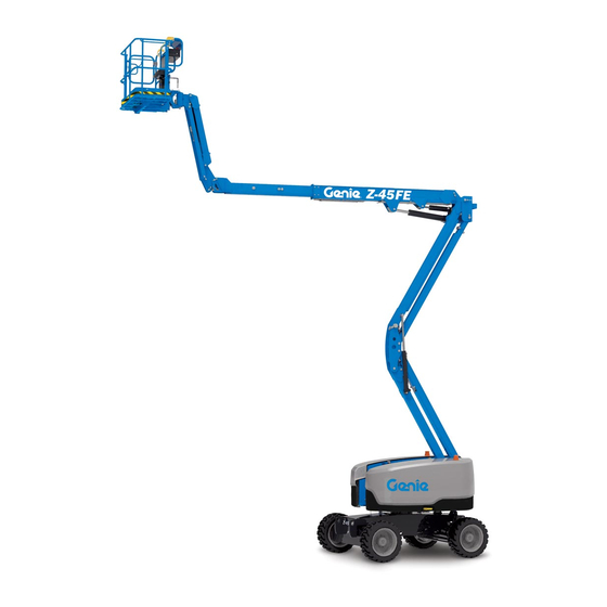
- Page 1 Operator's Manual Serial number range -45 FE ® ANSI/CSA From serial n.: Z45EM-101 North America South America -45 DC ® Asia with Maintenance Information First Edition First Printing Part No. 1299207GT...
-
Page 2: Table Of Contents
Specifications ............ 75 Copyright © 2019 by Terex Corporation First Edition: First Printing, January 2020 Genie and "Z" are registered trademarks of Terex South Dakota, Inc. in the U.S.A. and many other countries. These machines comply with ANSI/SAIA A 92.20 CAN/CSA B354.6... -
Page 3: Introduction
First Edition • First Printing Operator's Manual Introduction About this manual Intended Use and Familiarization Guide Genie appreciates your choice of our machine for your application. Our number one priority is user The intended use of this machine is to lift safety, which is best achieved by our joint efforts. - Page 4 Operator's Manual First Edition • First Printing Introduction Platform controls symbology and Ground controls symbology and related machine movement: related machine movement: Platform level Platform overload indicator light platform level, jib boom up/down, Secondary boom up/ primary boom down extend/retract, primary boom up/ down, secondary Primary boom up/...
- Page 5 First Edition • First Printing Operator's Manual Introduction Bulletin Distribution and Contacting the Manufacturer Compliance At times it may be necessary to contact Genie. When you do, be ready to supply the model number and Safety of product users is of paramount serial number of your machine, along with your name importance to Genie.
- Page 6 Operator's Manual First Edition • First Printing Introduction Safety Sign Maintenance Replace any missing or damaged safety signs. Keep operator safety in mind at all times. Use mild soap and water to clean safety signs. Do not use solvent-based cleaners because they may damage the safety sign material.
-
Page 7: Symbol And Hazard Pictorials Definitions
First Edition • First Printing Operator's Manual Symbol and Hazard Pictorials Definitions Crush hazard Keep away from Read the Overhead Collision hazard moving parts operator's manual obstruction Electrocution Maintain required Tip-over hazard Tip-over hazard Tip-over hazard hazard clearance Electrocution Avoid contact Disconnect battery Wind speed Machine not level... - Page 8 Operator's Manual First Edition • First Printing Symbol and Hazard Pictorials Definitions Wheel load Tire specifications No smoking Explosion hazard Fire hazard Platform tie-down Lifting & tie down Lanyard anchorage Tie-down point Lifting point instructions instructions points Maximum capacity Runaway hazard Color coded Voltage rating for Pressure rating for...
- Page 9 First Edition • First Printing Operator's Manual Symbol and Hazard Pictorials Definitions Replace damaged Batteries used as Read the service Battery box torque Crush Hazard wires and cords counterweights manual Keep hands clear Crush hazard Support the Emergency of moving parts platform or lowering during equipment...
-
Page 10: General Safety
Operator's Manual First Edition • First Printing General Safety Z-45 DC 31060 52865 1263543 97865 114390 31060 1301780 1298002 1267121 219484 219484 219484 1301780 114390 DANGER RT Tires Tire size: 315/55D20 minimum 12 ply Tip-over Hazard Foam-Filled Tire, Do not use air-fi lled tires. Minimum New Weight: 290 lbs / 131 kg Wheel Lug Torque... - Page 11 First Edition • First Printing Operator's Manual General Safety Z-45 DC 114397 31060 219487 218559 1288849 114390 1294856 28236 82410 31060 219487 114397 DANGER Platform Overload Indicator Light Light flashing Tip-over Hazard indicates the platform Altering or disabling sensors is overloaded. or limit switches can result in The engine will stop and no functions will...
- Page 12 Operator's Manual First Edition • First Printing General Safety Z-45 DC 114390 1263543 97865 31788 1297996 1297716 219484 31508 219484 114390 31788 31508 DANGER Maintain required clearance. Line Voltage Required Clearance Electrocution Hazard This machine is not electrically insulated. Death or 50 to 200KV 15 ft 4.6 m...
- Page 13 First Edition • First Printing Operator's Manual General Safety Z-45 FE 97602 1263543 97865 31060 114390 1301780 31060 114258 1298002 31060 1267121 219484 219484 52865 31060 97865 219484 1267121 DANGER RT Tires Tire size: 315/55D20 minimum 12 ply Tip-over Hazard Tip-over Hazard Foam-Filled Tire, Do not use air-fi...
- Page 14 Operator's Manual First Edition • First Printing General Safety Z-45 FE 114397 31060 219487 218559 1288849 114390 1294856 28236 82410 31060 219487 114397 DANGER Platform Overload Indicator Light Light flashing Tip-over Hazard indicates the platform Altering or disabling sensors is overloaded. or limit switches can result in The engine will stop and no functions will...
- Page 15 First Edition • First Printing Operator's Manual General Safety Z-45 FE 97865 114390 1263543 114258 31788 1297716 219484 31508 219484 1297996 114390 31788 31508 DANGER Maintain required clearance. Line Voltage Required Clearance Electrocution Hazard This machine is not electrically insulated. Death or 50 to 200KV 15 ft 4.6 m...
- Page 16 Operator's Manual First Edition • First Printing General Safety Z-45 DC 1263542 133205 114252 114249 133067 1256425 1299209 1286362 114249 General Safety 114252 133067 0 to 50KV 3.0 m 50 to 200KV 4.6 m 200 to 350KV 6.1 m 350 to 500KV 7.6 m 114252 500 to 750KV...
- Page 17 First Edition • First Printing Operator's Manual General Safety Z-45 DC 114252 114248 219956 219958 1272738 133067 1294857 82487 219958 133067 0 to 50KV 3.0 m 50 to 200KV 4.6 m 200 to 350KV 6.1 m 350 to 500KV 7.6 m 500 to 750KV 10.6 m 750 to 1000KV...
- Page 18 Operator's Manual First Edition • First Printing General Safety Z-45 DC 114252 133067 1294848 0 to 50KV 3.0 m > = 50 to 200KV 4.6 m 983 lbs / 200 to 350KV 6.1 m 1294848 A 446 kg 350 to 500KV 7.6 m 114252 500 to 750KV...
- Page 19 First Edition • First Printing Operator's Manual General Safety Z-45 FE 1263542 133205 114252 114249 114251 133067 1256425 1299209 1286362 114249 General Safety 114252 133067 0 to 50KV 3.0 m 50 to 200KV 4.6 m 200 to 350KV 6.1 m 350 to 500KV 7.6 m 500 to 750KV...
- Page 20 Operator's Manual First Edition • First Printing General Safety Z-45 FE 114252 114248 219956 219958 1272738 133067 1294857 82487 219958 133067 0 to 50KV 3.0 m 50 to 200KV 4.6 m 200 to 350KV 6.1 m 350 to 500KV 7.6 m 500 to 750KV 10.6 m 750 to 1000KV...
- Page 21 First Edition • First Printing Operator's Manual General Safety Z-45 FE 114252 133067 1294848 > = 0 to 50KV 3.0 m 983 lbs / 50 to 200KV 4.6 m 200 to 350KV 6.1 m 1294848 A 446 kg 114252 350 to 500KV 7.6 m 500 to 750KV 10.6 m...
-
Page 22: Personal Safety
Operator's Manual First Edition • First Printing Personal Safety Personal Fall Protection Personal fall protection equipment (PFPE) is required when operating this machine. Occupants must wear a safety belt or harness in accordance with governmental regulations. Attach the lanyard to the anchor provided in the platform. Operators must comply with employer, job site and governmental rules regarding the use of personal protective equipment. -
Page 23: Work Area Safety
First Edition • First Printing Operator's Manual Work Area Safety Electrocution Hazards Tip-over Hazards This machine is not electrically insulated and will not Occupants, equipment and materials shall not provide protection from contact with or proximity to exceed the maximum platform capacity or the electrical current. - Page 24 Operator's Manual First Edition • First Printing Work Area Safety If the tilt alarm sounds while the boom is lowered: Do not raise the boom when do not extend, rotate or raise the boom above wind speeds may exceed horizontal. Move the machine to a firm, level 12.5 m/s.
- Page 25 First Edition • First Printing Operator's Manual Work Area Safety Do not tie the boom or platform to adjacent Do not place ladders or structures. scaffolds in the platform or against any part of this Do not place loads outside the platform perimeter. machine.
- Page 26 Operator's Manual First Edition • First Printing Work Area Safety Do not climb down from Operation on Slopes Hazards the platform when raised. Do not drive the machine on a slope that exceeds the maximum uphill, downhill or side slope rating of the machine.
- Page 27 First Edition • First Printing Operator's Manual Work Area Safety Be aware of crushing Bodily Injury Hazard hazards when grasping the platform guard rail. Do not operate the machine with a hydraulic oil or air leak. An air leak or hydraulic leak can penetrate and/or burn skin.
- Page 28 Operator's Manual First Edition • First Printing Work Area Safety Damaged Machine Hazards Battery Safety Do not use a damaged or malfunctioning machine. Burn Hazards Conduct a thorough pre-operation inspection of Batteries contain acid the machine and test all functions before each Always wear protective work shift.
- Page 29 First Edition • First Printing Operator's Manual Work Area Safety Component Damage Hazards Contact Alarm Safety Do not use any battery charger greater than 48V Read, understand and obey all warnings and to charge the batteries. instructions provided with the contact alarm. Disconnect the battery pack plug before removing Do not exceed the rated platform capacity.
- Page 30 Operator's Manual First Edition • First Printing Work Area Safety Pipe Cradle Safety Panel Cradle Safety Read, understand and obey all warnings and Read, understand and obey all warnings and instructions provided with the pipe cradles. instructions provided with the panel cradles. Do not exceed the rated platform capacity.
-
Page 31: Legend
First Edition • First Printing Operator's Manual Legend 1 Foot switch 8 Platform controls 2 Manual storage container 9 Primary boom 3 Sliding mid-rail 10 Secondary boom 4 Lanyard anchorage point 11 Ground controls 5 Swing gate 12 Steer tire 6 Jib boom 13 Non-steer tire 7 Platform... -
Page 32: Controls
Operator's Manual First Edition • First Printing Controls The ground control station is to be used as a means to raise the platform for storage purposes and for function tests. The ground control station can be used in the event of an emergency to rescue an incapacitated person in the platform. - Page 33 First Edition • First Printing Operator's Manual Controls Ground Control Panel 8 Red Emergency Stop button 1 Function enable button Push in the red Emergency Stop button to the off position to stop all functions and turn Press and hold the function enable button to the engine off.
- Page 34 Operator's Manual First Edition • First Printing Controls 15 Platform rotate switch Move the platform rotate switch down and the platform will rotate to the right. Move the platform rotate switch up and the platform will rotate to the left. 16 Auxiliary power switch Use auxiliary power if the primary power source (engine) is not available.
- Page 35 First Edition • First Printing Operator's Manual Controls Platform Control Panel 12 Drive enable indicator light 1 Horn button 13 Drive enable switch 2 Platform level switch 14 Drive speed select switch 3 Jib boom up/down switch 15 Machine not level indicator light 4 Platform rotate switch 16 LCD readout screen 5 Primary boom extend/retract switch...
- Page 36 Operator's Manual First Edition • First Printing Controls -45 FE • Z -45 DC Part No. 1299207GT ® ®...
- Page 37 First Edition • First Printing Operator's Manual Controls Platform Control Panel Note: Function speeds will increase or decrease by 5% each time the speed control 1 Horn button switch is moved. The speed control switch can also be held in either direction to increase or Press this button and the horn will sound.
- Page 38 Operator's Manual First Edition • First Printing Controls Move the control handle in the direction 16 LCD readout screen indicated by the blue arrow on the control panel and the machine will drive forward. Move the control handle in the direction indicated by the yellow arrow and the machine will drive backwards.
- Page 39 First Edition • First Printing Operator's Manual Controls 20 Dual axis proportional control handle for primary boom up/down and turntable rotate left/right functions Move the control handle up and the primary boom will raise. Move the control handle down and the primary boom will lower.
-
Page 40: Inspections
Operator's Manual First Edition • First Printing Inspections Pre-operation Inspection Fundamentals It is the responsibility of the operator to perform a pre-operation inspection and routine maintenance. The pre-operation inspection is a visual inspection performed by the operator prior to each work shift. The inspection is designed to discover if anything Do Not Operate Unless: is apparently wrong with a machine before the... - Page 41 First Edition • First Printing Operator's Manual Inspections Pre-operation Inspection Nuts, bolts and other fasteners Platform entry mid-rail or gate Be sure that the operator’s, safety and Platform load cell responsibilities manuals are complete, legible and in the storage container located in the Lanyard anchorage points platform.
- Page 42 Operator's Manual First Edition • First Printing Inspections Function Test Fundamentals The function tests are designed to discover any malfunctions before the machine is put into service. The operator must follow the step-by-step instructions to test all machine functions. A malfunctioning machine must never be used. If Do Not Operate Unless: malfunctions are discovered, the machine must be tagged and removed from service.
- Page 43 First Edition • First Printing Operator's Manual Inspections At the Ground Controls Test Auxiliary Controls FE Models: 1 Select a test area that is firm, level and free of obstruction. 10 Turn the key switch to ground control. 2 Turn the key switch to ground control. 11 Pull out the red Emergency Stop button to the 3 Pull out the red Emergency Stop button to the on position.
- Page 44 Operator's Manual First Edition • First Printing Inspections Test the Foot Switch 21 Start the engine. See Operating Instructions section. DC Models: Result: At machine start up the ground control meter displays pitch and roll angles of the 32 Do not press down the foot switch. Test each machine and the alarm will beep 4 seconds.
- Page 45 First Edition • First Printing Operator's Manual Inspections Test the Steering Test the Drive Enable System 41 Press down the foot switch. 47 Press down the foot switch and lower the boom to the stowed position. 42 Press the thumb rocker switch on top of the drive control handle in the direction indicated 48 Rotate the turntable until the primary boom by the blue triangle on the control panel OR...
- Page 46 Operator's Manual First Edition • First Printing Inspections Test Limited Drive Speed Test Drive Tilt Cutout 51 Press down the foot switch. 61 Press down the foot switch. 52 Raise the primary boom approximately 61 cm. 62 With the boom fully stowed, drive the machine onto a slope where the chassis pitch angle is 53 Slowly move the drive control handle to the full greater than 4.5°.
- Page 47 First Edition • First Printing Operator's Manual Inspections 72 Drive the machine onto a slope where the 82 With the boom fully stowed, drive the machine chassis pitch angle is greater than 4.5°. onto a slope where the chassis roll angle is greater than 4.5°.
- Page 48 Operator's Manual First Edition • First Printing Inspections Test Auxiliary Controls Test the Contact Alarm (if equipped) 89 Push in the red Emergency Stop button to the 95 Do not activate the foot switch and press on off position. the contact alarm cable to release the actuator from the switch socket.
- Page 49 First Edition • First Printing Operator's Manual Inspections Test Aircraft Protection Package 100 Insert the actuator into the switch socket. Result: The lights and horn will turn off. (if equipped) 101 Operate each machine function. Note: Two people may be required to perform this test.
- Page 50 Operator's Manual First Edition • First Printing Inspections Workplace Inspection Checklist Be aware of and avoid the following hazardous situations: drop-offs or holes bumps, floor obstructions or debris Do Not Operate Unless: sloped surfaces unstable or slippery surfaces You learn and practice the principles of safe machine operation contained in this operator’s overhead obstructions and high voltage manual.
- Page 51 First Edition • First Printing Operator's Manual Inspections Inspection for Decals with Part No. Decal Description Words Z-45 DC 1263543 Decal,Compartment Access 1265361 Decal, Battery Charger Indicat Use the pictures on the next page to verify that all 1265450 Decal, Ground Control Box, Z60 decals are legible and in place.
- Page 52 Operator's Manual First Edition • First Printing Inspections 1265451 31060 1263543 97865 114390 31060 1301780 *82366 *72999 *82161 *1271943 1298002 *1271944 1267121 31060 *28174 *28235 1294398 *44981 52865 72086 72086 52475 219484 52475 219484 1294851 1294851 1294855 219487 218559 114397 1288849 *44981 27205...
- Page 53 First Edition • First Printing Operator's Manual Inspections Inspection for Decals with Part No. Decal Description Words Z-45 FE 219487 Decal,Platform Overload 826345 Decal,Uls Diesel Only,Tier 4 Use the pictures on the next page to verify that all 1263543 Decal,Compartment Access decals are legible and in place.Below is a numerical 1265361 Decal, Battery Charger Indicat...
- Page 54 Operator's Manual First Edition • First Printing Inspections 1265451 31060 114258 1263543 97865 114390 31060 1301780 *82366 *72999 *82161 *1271943 1298002 *1271944 1267121 31060 *28174 1294398 *28235 *44981 52865 72086 72086 52475 219484 52475 1269247 97602 219484 1294851 1294851 1294855 219487 218559 114397...
- Page 55 First Edition • First Printing Operator's Manual Inspections Inspection for Decals with Part No. Decal Description Symbols Z-45 DC Label – Instruction, Actuator Switch 1278982 Socket Use the pictures on the next page to verify that all 1299837 Label – 104 DB decals are legible and in place.
- Page 56 Operator's Manual First Edition • First Printing Inspections 1265451 114252 1299837 1256425 1263542 133205 133067 1294855 1286362 114249 1294851 72086 *1271943 *1271944 52475 *28174 *28235 *44981 72086 114248 219956 52475 219958 1294851 1272738 114249 44981 27205 27207 114252 27206 1281175 27206 133067 27207...
- Page 57 First Edition • First Printing Operator's Manual Inspections Inspection for Decals with Part No. Decal Description Symbols Z-45 FE 1278542 Label – Instruction, Contact Alarm Label – Instruction, Actuator Switch 1278982 Use the pictures on the next page to verify that all Socket decals are legible and in place.
- Page 58 Operator's Manual First Edition • First Printing Inspections 1265451 114252 1256425 114251 1299837 1263542 133205 133067 1294855 1286362 114249 1294851 72086 *1271943 52475 *1271944 *28174 *28235 *44981 72086 114248 52475 219956 219958 1294851 1272738 114249 44981 27205 27207 114252 27206 1281175 27206 133067...
-
Page 59: Operating Instructions
First Edition • First Printing Operator's Manual Operating Instructions Fundamentals The Operating Instructions section provides instructions for each aspect of machine operation. It is the operator’s responsibility to follow all the safety rules and instructions in the operator’s, safety and responsibilities manuals. Do Not Operate Unless: Using the machine for anything other than lifting personnel, along with their tools and materials, to... - Page 60 Operator's Manual First Edition • First Printing Operating Instructions Machine Operation Auxiliary Power FE models can be operated with or without the Use auxiliary power if the primary power source is engine running. not available. 1 Turn the key switch to ground or platform 1 Turn the key switch to ground or platform control.
- Page 61 First Edition • First Printing Operator's Manual Operating Instructions FE Models: Starting the Engine Operation from Ground 1 Turn the key switch to ground control. From the ground control panel: 2 Pull out the red Emergency Stop button to the 1 Turn the key switch to ground control.
- Page 62 Operator's Manual First Edition • First Printing Operating Instructions Operation from Platform To Steer 1 Press down the foot switch. Note: When operating the machine from the platform, the following foot switch messages may 2 Slowly move the drive control handle in the appear on the platform control LCD screen.
- Page 63 First Edition • First Printing Operator's Manual Operating Instructions To determine the slope grade: Driving on a slope Measure the slope with a digital inclinometer OR use Determine the uphill, downhill and side slope the following procedure. ratings for the machine and determine the slope grade.
- Page 64 Operator's Manual First Edition • First Printing Operating Instructions Drive Enable Function Speed Control 1 Move the switch to Light on indicates that the boom the left to decrease has moved just past either the function speeds non-steer wheel and the drive for jib up/down, function has been interrupted.
- Page 65 First Edition • First Printing Operator's Manual Operating Instructions Machine Not Level Indicator Light Platform Overload Indicator Light If the tilt alarm sounds when the Light flashing indicates the platform is raised, the Machine Not platform is overloaded and Level indicator light will come on no functions will operate.
- Page 66 Operator's Manual First Edition • First Printing Operating Instructions Contact Alarm (if equipped) Aircraft Protection Package (if equipped) The contact alarm is designed to alert ground If the platform bumper comes personnel when an operator makes contact with into contact with an object, the platform control panel, interrupting boom the machine will shut down movement, sounding an alarm and flashing...
- Page 67 First Edition • First Printing Operator's Manual Operating Instructions After the charge cycle reaches 85% the platform control panel LCD screen will display the following message, HYBRID CHARGE COMPLETE. PLUG IN FOR 100% CHARGE Charging Batteries with External Power Battery and Charger Instructions Observe and Obey: 1 Connect the battery charger to a grounded AC circuit.
- Page 68 Operator's Manual First Edition • First Printing Operating Instructions Pipe Cradle Instructions Observe and Obey: Pipe cradles must be installed on the inside of The pipe cradle assembly consists of 2 pipe the platform. cradles positioned at either side of the platform and mounted to the guardrails with U-bolts.
- Page 69 First Edition • First Printing Operator's Manual Operating Instructions Pipe Cradle Operation Panel Cradle Assembly 1 Be sure the pipe cradle assembly and 1 Apply the warning decal to the front of each installation instructions have been followed panel cradle (if needed). properly and that the pipe cradles are secured 2 Install rubber bumper 1 in the panel cradle to the platform railings.
- Page 70 Operator's Manual First Edition • First Printing Operating Instructions Installation of Padding 1 Install the 2 pieces of padding on the platform rails. Position the padding to protect the panels rubber from contact with the platform rails. bumper 2 Installation of Strap 1 Open the clamp and install it around a vertical rubber platform rail tube.
-
Page 71: Transport And Lifting Instructions
First Edition • First Printing Operator's Manual Transport and Lifting Instructions Be sure the turntable is secured with the turntable rotation lock before transporting. Be sure the unlock the turntable for operation. Do not drive the machine on a slope that exceeds the uphill, downhill or side slope rating. - Page 72 Operator's Manual First Edition • First Printing Transport and Lifting Instructions Securing to Truck or Trailer for Securing the Chassis Transit Use chains of ample load capacity. Always use the turntable rotation lock pin each Use a minimum of 4 chains or straps. time the machine is transported.
- Page 73 First Edition • First Printing Operator's Manual Transport and Lifting Instructions Lifting Instructions Fully lower and retract the boom. Fully lower the jib. Remove all loose items on the machine. Rotate 90° the swing chassis, from the transport position. Observe and Obey: Determine the center of gravity of your machine using the table and the picture on this page.
-
Page 74: Maintenance
Operator's Manual First Edition • First Printing Maintenance Check the Engine Oil Level Maintaining the proper engine oil level is essential Observe and Obey: to good engine performance and service life. Operating the machine with an improper oil level Only routine maintenance items specified in can damage engine components. - Page 75 First Edition • First Printing Operator's Manual Maintenance Check the Hydraulic Oil Level Check the Engine Coolant Level – Liquid Cooled Models Maintaining the hydraulic oil at the proper level is essential to machine operation. Improper hydraulic Maintaining the engine coolant at the proper level oil levels can damage hydraulic components.
- Page 76 Operator's Manual First Edition • First Printing Maintenance Check the Batteries Scheduled Maintenance Maintenance performed quarterly, annually and every two years must be completed by a person trained and qualified to perform maintenance on this machine according to the procedures found in Proper battery condition is essential to good the service manual for this machine.
-
Page 77: Specifications
First Edition • First Printing Operator's Manual Specifications Z-45 DC Airborne noise emissions Height, working maximum 15.92 m Sound pressure level at ground <70 dBA workstation Height, platform maximum 13.92 m Sound pressure level at platform <70 dBA Height, stowed maximum 2.29 m workstation Horizontal reach, maximum... - Page 78 Operator's Manual First Edition • First Printing Specifications Z-45 FE Airborne noise emissions Height, working maximum 15.92 m Sound pressure level at ground <80.3 dBA workstation Height, platform maximum 13.92 m Sound pressure level at platform <76 dBA Height, stowed maximum 2.30 m workstation Horizontal reach, maximum...
- Page 79 First Edition • First Printing Operator's Manual Specifications Z-45 FE Range of Motion Chart Z-45 FE Range of Motion Chart with Aircraft Protection Part No. 1299207GT -45 FE • Z -45 DC ® ®...
- Page 80 California Proposition 65 WARNING Operating, servicing and maintaining this equipment, passenger vehicle or off-highway motor vehicle can expose you to chemicals including engine exhaust, carbon monoxide, phthalates, and lead, which are known to the State of California to cause cancer and birth defects or other reproductive harm.
Need help?
Do you have a question about the Genie Z-45 FE and is the answer not in the manual?
Questions and answers