Table of Contents
Advertisement
Quick Links
Service Manual
EN
E2-30
• 107071 (EU Model)
• 107074 (USA Model)
• 107075 (Japan Model)
It is the Customer's responsibility to have all operators and service personnel read and understand this
Contact your local Carlisle Fluid Technologies representative for additional copies of this manual.
READ ALL INSTRUCTIONS BEFORE OPERATING THIS PRODUCT
77-3215 R5.5
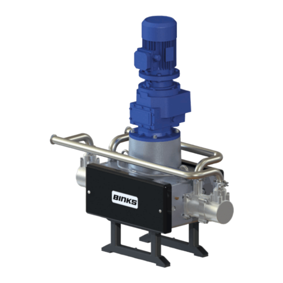
E2-30/40 Electric Drive
IMPORTANT! DO NOT DESTROY
manual.
Pump
E2-40
• 107093 (EU Model)
• 107094 (USA Model)
• 107095 (Japan Model)
1/40
www.carlisleft.com
Advertisement
Table of Contents

Related Manuals for Carlisle Fluid Technologies Binks E2-30


Summary of Contents for Carlisle Fluid Technologies Binks E2-30
- Page 1 IMPORTANT! DO NOT DESTROY It is the Customer's responsibility to have all operators and service personnel read and understand this manual. Contact your local Carlisle Fluid Technologies representative for additional copies of this manual. READ ALL INSTRUCTIONS BEFORE OPERATING THIS PRODUCT 77-3215 R5.5 1/40 www.carlisleft.com...
-
Page 2: Eu Declaration Of Conformity
II 2 GD ck T4 (Gearbox) Notified body details and role: Element Materials Technology (0891) Lodging of Technical file This Declaration of conformity / incorporation Carlisle Fluid Technologies UK Ltd, is issued under the sole responsibility of the Ringwood Road, manufacturer: Bournemouth, BH11 9LH. UK EU Declaration of Conformity ... - Page 3 In this part sheet, the words WARNING, CAUTION and NOTE are used to emphasize important safety information as follows: WARNING CAUTION NOTE Hazards or unsafe practices which could result in Hazards or unsafe practices which could result in Important installation, operation or maintenance severe personal injury, death or substantial property minor personal injury, product or property information.
-
Page 4: Specification
SPECIFICATION Nominal pump stroke: 50mm [1.97 ins] E2-30* Maximum fluid pressure: 20.7 bar [300psi] E2-40* Maximum fluid pressure: 16 bar [232psi] E2-30 Nominal flow volume / cycle: 0.75 l/m [0.20 US gal/m] E2-40 Nominal flow volume / cycle: 1.00 l/m [0.26 US gal/m] E2-30 Fluid Output @ 20 HZ [10 cycles/min] 7.5 l/m [2.0 US gal/m] E2-40 Fluid Output @ 20 HZ [10 cycles/min]... -
Page 5: Dimensions And Mounting Details
DIMENSIONS AND MOUNTING DETAILS M6 HEX. Head screw for pump earth grounding; the Pump Frame must be wired to a suitable earth ground to ensure that there is no possibility of static build up. 77-3215 R5.5 5/40 www.carlisleft.com... -
Page 6: Installation
INSTALLATION The Pump Units are designed for location in Zone 1 Hazardous areas, ATEX Category 2. Electrical connections must be in accordance with Local Regulations for installation in Hazardous Areas. It is recommended that a Local Control Box is positioned in close proximity to the pump, as a convenient local Start / Stop facility and Junction box. -
Page 7: Electric Motor
INSTALLATION Electric Motor The motor must be wired to provide a clockwise direction of the cam. Electric Motors for hazardous areas are specially designed to comply with official regulations concerning the risk of explosion. If improperly used, badly connected, or altered no matter how minor, their reliability could be in doubt. Standards relating to the connection and use of electrical apparatus in hazardous areas must be taken into consideration. - Page 8 INSTALLATION Attach suitable flexible hoses to the inlet and outlet connections. e.g., Suction - Ø50 I.D. [-1 to 10 bar working pressure] Outlet - Ø38 - 50 I.D. [20 bar working pressure] Ensure adequate air space around the Pump for maintenance and electric motor cooling requirements. ...
-
Page 9: System Operation
SYSTEM OPERATION Before starting:- Ensure all electrical and mechanical connections are correctly made. All required interlocks are tested and operational. Suitable material for pumping is available at the suction hose. The outlet connection is not blocked or isolated by any valves. ... -
Page 10: Parts List
PARTS LIST Pump Assembly ITEM PART NUMBER DESCRIPTION REMARKS 193709 E2-30/40 MECHANICAL ASSY EU MODEL 192669 H063 ATEX GEARBOX H063 GEARBOX USA MODEL 192670 (Not Shown) H063 GEARBOX JAPAN MODEL 192756 (Not Shown) EU MODEL 192666 1.5KW ATEX MOTOR 1.5KW ELECTRIC MOTOR USA MODEL 192667 (Not Shown) - Page 11 GREASE LOCTITE TORQUE MAINTENANCE ORDER (Reverse for assembly) GREASE INTERNAL (AGMD-010) 77-3215 R5.5 11/40 www.carlisleft.com...
- Page 12 PARTS LIST - PRV and Manifold Assembly ITEM PART NUMBER DESCRIPTION REMARKS 104168 E2-30 1.5'' PRESSURE RELIEF VALVE 22 bar 104201 E2-40 1.5'' PRESSURE RELIEF VALVE 16 bar 192008 1.5'' SANITARY GASKET - PTFE 192009 1 & 1 1/2 SANITARY CLAMP 193746 1.5'' SANITARY ELBOW 194275...
- Page 13 GREASE LOCTITE TORQUE MAINTENANCE ORDER (Reverse for assembly) GREASE INTERNAL (AGMD-010) 77-3215 R5.5 13/40 www.carlisleft.com...
-
Page 14: Mechanical Assembly
PARTS LIST Mechanical Assembly ITEM PART NUMBER DESCRIPTION REMARKS 163126 M12 HEXAGON NUT 163161 M8 NYLOC NUT 164470 M12 WASHER (ST ST) 165100 M16 SPRING WASHER 165108 M8 SPRING WASHER 165123 Ø10 SPRING WASHER 165371 M16 x 60 HEX HEAD BOLT (PLATED) 165552 M8 x 20 CAP HEAD SCREW 165588... - Page 15 PARTS LIST Mechanical Assembly ITEM PART NUMBER DESCRIPTION REMARKS 193104 CARRIAGE SPRING 193105 SPRING KEEP ASSEMBLY 193130 1/8''- 6 mm EXTENDED ELBOW 193131 Ø10 x 1/4'' BSPT EXT ELBOW 193696 Ø40 SHAFT COUPLING SPACER 194538 MAIN BODY MACHINING 194540 SPACER 194584 BELL HOUSING CAM ASSY 77-3215 R5.5...
- Page 16 GREASE LOCTITE TORQUE MAINTENANCE ORDER (Reverse for assembly) GREASE INTERNAL (AGMD-010) ** Tighten bolts holding carriage ends once pump is fully assembled. 77-3215 R5.5 16/40 www.carlisleft.com...
- Page 17 GREASE LOCTITE TORQUE MAINTENANCE ORDER (Reverse for assembly) GREASE INTERNAL NOTE: (AGMD-010) Part No. 1 Grease using 502375 Part No. 4 To be tightened using tool 193120 Part No. 6 To be tightened using tool 193119 Part No. 11 To be pressed into housing using tool 193121 Part No.
- Page 18 PARTS LIST Bell Housing & Shaft Assemblies ITEM PART NUMBER DESCRIPTION REMARKS 163951 M6 x 16 CAP HEAD SCREW 163952 M6 x 20 CAP HEAD SCREW 165087 M6 SPRING WASHER 192616 BEARING CAP 192617 BEARING CLAMP 192639 Ø50 x Ø110 x 44.4 SHAFT BEARING ...
- Page 19 77-3215 R5.5 19/40 www.carlisleft.com...
-
Page 20: Carriage Assembly
PARTS LIST Carriage Assembly ITEM PART NUMBER DESCRIPTION REMARKS 192608 LH CARRIAGE END 192607 CARRIAGE MIDDLE 192609 RH CARRIAGE END 192618 CARRIAGE ADAPTOR 192611 FOLLOWER GUARD WASHER 192610 CAM FOLLOWER PIN 192612 FOLLOWER NUT WASHER 192641 Ø72 CAM FOLLOWER ... - Page 21 When fitting new bearings: Ensure seals have been removed from inside of bearing to ensure a correct grease supply path via centre spacer. Bolts remain loose, tightened when mechanical assembly is complete. Orientate bearing so black section along the body is aligned to the block's side.
- Page 22 PARTS LIST E2-30 Fluid Section ITEM PART NUMBER DESCRIPTION REMARKS 160513 BALL CHECK SPRING 163921 M6 x 25 CAP HEAD SCREW 164472 M8 x 25 CAP HEAD SCREW 165044 M12 SPRING WASHER 165087 M6 SPRING WASHER 165108 M8 SPRING WASHER 165960 M12 x 40 CAP HEAD SCREW 171788...
- Page 23 GREASE LOCTITE TORQUE MAINTENANCE ORDER (Reverse for assembly) GREASE INTERNAL (AGMD-010) 77-3215 R5.5 23/40 www.carlisleft.com...
- Page 24 PARTS LIST E2-40 Fluid Section ITEM PART NUMBER DESCRIPTION REMARKS 160513 BALL CHECK SPRING 163921 M6 x 25 CAP HEAD SCREW 164472 M8 x 25 CAP HEAD SCREW 165044 M12 x 40 SPRING WASHER 165108 M8 SPRING WASHER 165960 M12 x 40 CAP HEAD SCREW 165087 M6 x 25 SPRING WASHER...
- Page 25 GREASE LOCTITE TORQUE MAINTENANCE ORDER (Reverse for assembly) GREASE INTERNAL (AGMD-010) 77-3215 R5.5 25/40 www.carlisleft.com...
- Page 26 PARTS LIST E2-30 Piston Assembly ITEM PART NUMBER DESCRIPTION REMARKS 160513 BALL CHECK SPRING 162805 63.17 x 2.62 O-RING 162807 50.52 x 1.78 O-RING 162854 82.22 x 2.62 O-RING 171784 1.75 ST ST BALL 192629 INLET SPRING KEEP ...
- Page 27 PARTS LIST E2-40 Piston Assembly ITEM PART NUMBER DESCRIPTION REMARKS BALL CHECK SPRING 160513 162805 63.17 x 2.62 O-RING 162807 50.52 x 1.78 O-RING 162854 82.22 x 2.62 O-RING 171784 1.75 ST ST BALL 192629 INLET SPRING KEEP ...
- Page 28 PARTS LIST Shaft & Bellows Assembly ITEM PART NUMBER DESCRIPTION REMARKS 192374 RETAINING NUT 192579 KNIFED BELLOWS 192627 BELLOWS SPACER 192628 SHAFT SEAL 192619 PISTON SHAFT 502377 BELLOWS POSITIONING TOOL TOOL 502382 BELLOWS ASSEMBLY SPIGOT TOOL Screw Item No. 2 (assembly spigot) onto the piston shaft (grease spigot with AMGD-010).
-
Page 29: General Maintenance
Maintenance General Maintenance The working life and thus the expected life prior to replacement of parts within a Paint Pump are greatly affected by three main factors: - • Abrasiveness of Fluid Pumped Pump Duty Cycle • Fluid Pressure Output Requirement •... -
Page 30: Operation
Maintenance Maintenance schedule Inspection Operation Daily Check for any fluid leakage Check for any excessive mechanical noise Check for excessive fluid pressure pulsation Weekly Check oil level within gearbox While running, apply (502375) grease to cam follower bearings, 8 strokes of a 3 Monthly standard ‘cartridge’... - Page 31 Maintenance Gearbox WARNING Wait until the unit has cooled sufficiently after stopping and isolation. Gearbox Every 1000 hours verify the good condition of oil seals and gaskets Maintenance The gearbox is supplied factory fitted with oil and is a service free unit. However if seals start to leak and oil level is reduced, both the affected seal and oil need to be replaced as a general overhaul of the unit.
-
Page 32: Electric Motors
Maintenance Motor WARNING Wait until the unit has cooled sufficiently after stopping and isolation. Electric Motors Maintenance of Ex Motors - are reported by EN 60079-17 standard, in particular:- • The electric connections must be correctly locked to avoid resistance-increases, with consequent contact overheating. -
Page 33: Fault Finding
Fault Finding Mechanics Symptom Possible Cause Remedy Gearbox Output shaft does not Drive between shafts in the gear unit Return the unit for repair and replace rotate, even though the motor is interrupted gearbox running. Gearbox Oil leaking Defective gasket on gear unit Retighten screws on gear cover. - Page 34 Fault Finding Fluid Section Symptom Possible Cause Remedy Air entering the suction Check o-rings and hose hose/manifold connections Worn piston seals Replace piston seals. Pump will not ‘Prime’ Ball checks not seating Inspect, clean and/or replace correctly. balls and seats. No power Check electrical supply Inverter Unit or safety...
- Page 35 Testing and Lubricating Testing and Lubricating after major overhaul WARNING Testing and Lubricating - Qualified personnel only Connect pump to paint system. Connect electric motor to a suitable electrical supply. Fit the gearbox vent plug. Turn on paint system and set back pressure regulator to zero. Turn the pump on at the local isolation mounted switch.
-
Page 36: Spare Parts List
Spare Parts List Recommended Replacement Spare Parts and Kits for E2-30/40 Pumps KIT No. Part No. Description Remarks 192600 Constant Velocity Cam 193626 Ø100 Piston E2-30 194112 Ø114 Piston E2-40 250768** Fluid section seal kit E2-30 250796** Fluid section seal kit E2-40 ... - Page 37 ACCESSORIES PART NUMBER DESCRIPTION REMARKS 192800 Smart Card 502501 BPR Control Box 502483 Electrical Panel for Single Pump Operation Inc. Smart Card Grease Gun for Cam Follower 502373 Collet Connector (& Main Bearings) Grease Gun for Linear Bearings 502514 Hook Connector (300mm Extension) Grease for Cam Follower 502375...
- Page 38 ACCESSORIES PART NUMBER DESCRIPTION REMARKS 192450 M8 Torx Security Screwdriver for Cover FOC with a New Pump 502508 Top Bearing Locknut Tool 502509 Bottom Bearing Locknut Tool 502510 Top Bearing Press Tool 502511 Bottom Bearing Press Tool 502512 Shaft Assembly Tool 502377 Bellows Assembly Tool 502382...
- Page 39 NOTES 77-3215 R5.5 39/40 www.carlisleft.com...
- Page 40 WARRANTY POLICY This product is covered by Carlisle Fluid Technologies’ materials and workmanship limited warranty. The use of any parts or accessories, from a source other than Carlisle Fluid Technologies, will void all warranties. Failure to reasonably follow any maintenance guidance provided, may invalidate any warranty.
Need help?
Do you have a question about the Binks E2-30 and is the answer not in the manual?
Questions and answers