Table of Contents
Advertisement
Change for life
Thank you for choosing our product.
For proper operation, please read and keep this manual carefully.
If you have lost the Owner's Manual, please contact the local
agent or visit www.gree.com or sent email to global@gree.com.cn or electronic version.
GREE reserves the right to interpret this manual which will be subject to any change due
to product improvement without further notice.
GREE Electric Appliances, Inc. of Zhuhai reserves the final right to interpret this manual.
DC Inverter U-match Series
Cassette Type Unit
Installation Manual
Air Conditioners
Models
Indoor Unit
Outdoor Unit
GKH12K3FI
GUHD12NK3FO
GKH18K3FI
GUHD18NK3FO
GKH24K3FI
GUHD24NK3FO
GKH30K3FI
GUHD30NK3FO
GKH36K3FI
GUHD36NK3FO
GKH42K3FI
GUHD42NK3FO
GKH48K3FI
GUHD48NK3FO
GKH36K3FI
GUHD36NM3FO
GKH42K3FI
GUHD42NM3FO
GKH48K3FI
GUHD48NM3FO
GKH60K3FI
GUHD60NM3FO
Advertisement
Table of Contents

Related Manuals for Gree GKH12K3FI


Summary of Contents for Gree GKH12K3FI
- Page 1 If you have lost the Owner’s Manual, please contact the local agent or visit www.gree.com or sent email to global@gree.com.cn or electronic version. GREE reserves the right to interpret this manual which will be subject to any change due to product improvement without further notice.
-
Page 2: Table Of Contents
Contents 1 Safety Precautions ..................1 2 Outline of the Unit and Main Parts..............3 3 Preparative for Installation ................4 3.1 Standard Accessory Parts ................4 3.2 Selection of the Installation Location ............5 3.3 Connection Pipe Requirement ..............7 3.4 Electrical Requirement ................ -
Page 3: Safety Precautions
DC Inverter U-match Series Cassette Type Unit 1 Safety Precautions This mark indicates procedures which, if improperly performed, might lead to the WARNING! death or serious injury of the user. This mark indicates procedures which, if improperly performed, might possibly result CAUTION! in personal harm to the user, or damage to property. - Page 4 DC Inverter U-match Series Cassette Type Unit (14). During installation, attach the refrigerant piping securely before running the compressor. If the compressor is not attached and the stop valve is open during pump-down, air will be sucked in when the compressor is run, causing abnormal pressure in the freezer cycle which will lead to breakage and even injury.
-
Page 5: Outline Of The Unit And Main Parts
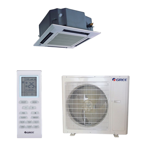
DC Inverter U-match Series Cassette Type Unit 2 Outline of the Unit and Main Parts Indoor 1. Drainage device 2. Drainage pipe 3. Air flow flap Outdoor 4. Connection pipe Air inlet 5. Wired Controller 6. Wireless Controller 7. Big handle 8. -
Page 6: Preparative For Installation
DC Inverter U-match Series Cassette Type Unit 3 Preparative for Installation 3.1 Standard Accessory Parts The standard accessory parts listed below are furnished and should be used as required. Table 1 Indoor Unit Accessories Name Appearance Q'ty Usage To connect with the hard PVC drain Drain Hose pipe To fix the hook on the cabinet of the... -
Page 7: Selection Of The Installation Location
DC Inverter U-match Series Cassette Type Unit 3.2 Selection of the Installation Location WARNING! The unit must be installed where strong enough to withstand the weight of the unit and fixed securely, otherwise the unit would topple or fall off. CAUTION! ①... - Page 8 DC Inverter U-match Series Cassette Type Unit Table 3 Models H(mm) GKH12K3FI GKH18K3FI GKH24K3FI GKH30K3FI GKH36K3FI GKH42K3FI GKH48K3FI GKH60K3FI Fig.2 3.2.2 Outdoor Unit WARNING! ① . Install the unit where it will not be tilted by more than 5°. ② . During installation, if the outdoor unit has to be exposed to strong wind, it must be fixed securely.
-
Page 9: Connection Pipe Requirement
Pipe(Inch) Pipe Difference between pipe(Outer Length Indoor Unit and Diameter × wall Model Liquid Outdoor Unit (m) thickness) (mm) GKH12K3FI GUHD12NK3FO GKH18K3FI GUHD18NK3FO GKH24K3FI GUHD24NK3FO GKH30K3FI GUHD30NK3FO GKH36K3FI GUHD36NK3FO GKH42K3FI GUHD42NK3FO Φ25×1.5 GKH48K3FI GUHD48NK3FO GKH36K3FI GUHD36NM3FO GKH42K3FI GUHD42NM3FO GKH48K3FI GUHD48NM3FO GKH60K3FI GUHD60NM3FO The connection pipe should be insulated with proper water-proof insulating material. - Page 10 DC Inverter U-match Series Cassette Type Unit Table 6 Minimum Sectional Area of Power Capability of Air Model Power Cable and Earth line Supply Switch(A) GUHD12NK3FO GUHD18NK3FO GUHD24NK3FO GUHD30NK3FO 220-240V~ 50Hz GUHD36NK3FO GUHD42NK3FO GUHD48NK3FO GUHD36NM3FO GUHD42NM3FO 380-415V 3N~ 50Hz GUHD48NM3FO GUHD60NM3FO Notes: The fuse is located on the main board.
-
Page 11: Installation Of The Unit
DC Inverter U-match Series Cassette Type Unit 4 Installation of the Unit 4.1 Installation of the Indoor Unit 4.1.1 Indoor unit dimension Fig.4 Table 7 Item Model GKH12K3FI GKH18K3FI GKH24K3FI GKH30K3FI GKH36K3FI GKH42K3FI GKH48K3FI 1040 GKH60K3FI 4.1.2 Installing the Main Body Unit... -
Page 12: Installation Of The Outdoor Unit
DC Inverter U-match Series Cassette Type Unit (1). Install the hoisting stand on the hoisting screw by using nuts and gaskets at both the upper and lower sides of the hoisting stand. To prevent the gasket from breaking off, a gasket anchor board can be helpful. - Page 13 DC Inverter U-match Series Cassette Type Unit 4.2.1 Outdoor unit dimension Fig.10 Table 8 Unit: mm Item Model GUHD12NK3FO GUHD18NK3FO GUHD24NK3FO GUHD30NK3FO GUHD36NK3FO 1107 1100 GUHD36NM3FO GUHD42NM3FO GUHD42NK3FO 1349 GUHD48NK3FO GUHD48NM3FO GUHD60NM3FO 1085 1365 4.2.2 Condensate Drainage of the Outdoor Unit(Only for the heat pump unit) (Fig.11) (1).
-
Page 14: Installation Of The Connection Pipe
DC Inverter U-match Series Cassette Type Unit Bottom Drain cap Drain pipe mounting hole Fig.11 4.3 Installation of the Connection Pipe 4.3.1 Flare Processing (1). Cut the connection pipe with the pipe cutter and remove the burrs. (2). Hold the pipe downward to prevent cuttings from entering the pipe. (3). - Page 15 DC Inverter U-match Series Cassette Type Unit CAUTION! ① . To prevent breaking of the pipe, avoid sharp bends. Bend the pipe with a radius of curvature of 150 mm or over. ② . If the pipe is bent repeatedly at the same place, it will break. 4.3.3 Connecting the Pipe at the Indoor Unit Side Detach the caps and plugs from the pipes.
- Page 16 DC Inverter U-match Series Cassette Type Unit Table 9 Flare nut tightening torque Pipe Diameter Tightening Torque 1/4˝(Inch) 15-30 (N·m) 3/8˝(Inch) 35-40 (N·m) 5/8˝(Inch) 60-65 (N·m) 1/2˝(Inch) 45-50 (N·m) 3/4˝(Inch) 70-75 (N·m) 7/8˝(Inch) 80-85 (N·m) CAUTION! Be sure to connect the gas pipe after connecting the liquid pipe completely. 4.3.4 Connecting the Pipe at the Outdoor Side Unit Tighten the flare nut of the connection pipe at the outdoor unit valve connector.
-
Page 17: Vacuum And Gas Leakage Inspection
DC Inverter U-match Series Cassette Type Unit 4.3.7Liquid Pipe and Drain Pipe Sealed If the outdoor unit is installed lower than the indoor unit (See Fig.18) Saddle (1). A drain pipe should be above ground and the end of the pipe does not dip into water. - Page 18 DC Inverter U-match Series Cassette Type Unit (5). The evacuation duration depends on the unit’s capacity, generally, 15 minutes for the 12K units, 20 minutes for the 18K units, 30 minutes for the 24/30/36K units, 45 minutes for the 42/48/60 units. And verify if the pressure gauge at the low pressure side of the manifold valve assembly reads -1.0Mp (-75cmHg), if not, it indicates there is leak somewhere.
-
Page 19: Installation Of The Drain Hose
DC Inverter U-match Series Cassette Type Unit When the height difference between the indoor unit and outdoor unit is larger than 10 meters, an oil bend should be employed for every 6 meters. Outdoor Oil bend Indoor Oil bend Fig.21 4.5 Installation of the Drain Hose 4.5.1 Installationof Drain Piping (1). - Page 20 DC Inverter U-match Series Cassette Type Unit Tighten the clamp until the screw head is less Insulate the pipe clamp and the drain hose using heat then 4mm from the hose. insulation sponge. Metal clamp Metal clamp (accessory) Drain hose (accessory) Insulation sponge (accessory) Grey tape (accessory) (3).
- Page 21 DC Inverter U-match Series Cassette Type Unit 3-way connection Connection of drain elbow of drainage pipe joint Connection of horizontal pipe Fig.27 Fig.28 Fig.29 4.5.3 Precautions When Doing Riser Piping Work (1). Make sure that heat insulation work is executed on the following 2 spots to prevent any possible water leakage due to dew condensation.
-
Page 22: The Panel Installation
DC Inverter U-match Series Cassette Type Unit Drain hose(attachment) Fig.32 4.5.4 Testing of Drain Piping After piping work is finished, check if drainage flows smoothly. Shown in the Fig.33, Add approximately 1liter of water slowly into the drain pan and check drainage flow during COOL running. - Page 23 DC Inverter U-match Series Cassette Type Unit (2). Improper screwing of the screws may cause the troubles shown in Fig.35. Condensate Fig.35 (3). If gap still exists between ceiling and decoration panel after tightening the screws, readjust the height of the indoor unit. (Fig.36) Fig.36 (4).
-
Page 24: Electrical Wiring
DC Inverter U-match Series Cassette Type Unit (4). Adjust the panel along the direction indicated by the arrow as shown in Fig.38. (5). Tighten the screws until the thickness of the sealing material between the panel and the indoor unit reduces to 5-8cm. Fig.38 4.7 Electrical Wiring 4.7.1 Wiring Precautions... - Page 25 DC Inverter U-match Series Cassette Type Unit ⑤ . Use a special branch circuit breaker and receptacle matched to the capacity of the air conditioner. ⑥ . The special branch circuit breaker is installed in the permanent wiring. Always use a circuit that can trip all the poles of the wiring and has an isolation distance of at least 3mm between the contacts of each pole.
- Page 26 ⑤ . Always fasten the outside covering of the connection cord with cord clamps. (If the insulator is not clamped, electric leakage may occur.) ⑥ . Always connect the ground wire. (4). Electric wiring between the indoor and outdoor units Single-phase units(12K~30K) GUHD12NK3FO+GKH12K3FI GUHD18NK3FO+GKH18K3FI ① . Power cord 3×1.5mm (H07RN-F) ② . Power cord 3×1.0mm (H05RN-F) ③...
- Page 27 DC Inverter U-match Series Cassette Type Unit Single-phase units(36K~48K) GUHD36NK3FO+GKH36K3FI GUHD42NK3FO+GKH42K3FI ① . Power cord 3×2.5mm (H07RN-F) ② . Power cord 3×1.0mm (H05RN-F) ③ . Communication Cords 2×0.75mm (H05RN-F) GUHD48NK3FO+GKH48K3FI ① . Power cord 3×6.0mm (H07RN-F) (H05RN-F) ② . Power cord 3×1.0mm ③...
- Page 28 DC Inverter U-match Series Cassette Type Unit CAUTION! ① . The power cord and the wire of the fresh air valve are high-voltage, while the communication cord and connection wire of the wired controller are low-voltage. They should run separately against electromagnetic interference.
-
Page 29: Installation Of Controllers
DC Inverter U-match Series Cassette Type Unit Three-phase: 36K~60K Fig.45 Routing of External Power Lines Power lines should go along the right side plate and be fixed to the fixation hook with binding wires to keep no contact with pipelines. Communication lines between indoor and outdoor units also should go along the right side plate and keep away from power lines. - Page 30 DC Inverter U-match Series Cassette Type Unit Indoor fan motor error Full water protection Indoor ambient temperature sensor error Evaporator temperature sensor error Condenser temperature sensor error Outdoor ambient temperature sensor error Discharge temperature sensor error Temperature sensor error of wired controller Capacity code error Outdoor memory chip error Electric box sensor error...
-
Page 31: Working Temperature Range
DC Inverter U-match Series Cassette Type Unit (2). Instructions to the Error Indicating Lamps on the Panel of the Cassette Type Unit. Receiver "88" Dispaly "Auto" Button Power Timer "Test" Button Indicating Lamp Indicating Lamp Fig.47 Power and ON/OFF Indicating Lamp: ◆... -
Page 32: Troubleshooting And Maintenance
Note: After carrying out the check of the above items and taking relevant measures to solve the problems but the air-conditioning unit still does not function well, please stop the operation of the unit immediately and contact the local service agency designated by Gree. Only ask professional serviceman to check and repair the unit. -
Page 33: Routine Maintenance
DC Inverter U-match Series Cassette Type Unit 7.2 Routine Maintenance Only a qualified service person is allowed to perform maintenance. Before accessing to terminal devices, all power supply circuits must be disconnected. Do not use water or air of 50°C or higher for cleaning air filters and outside panels. Notes: Do not operate the air conditioner with the filter uninstalled, otherwise dust would come into ①... - Page 34 DC Inverter U-match Series Cassette Type Unit 2. Disassemble the air inlet grille Open the air inlet grille at 45°, raise it and remove the grille. 3. Disassemble the filter screen Draw out the filter screen and remove it. Filter screen 4.
- Page 35 GREE ELECTRIC APPLIANCES, INC. OF ZHUHAI Add: West Jinji Rd, Qianshan, Zhuhai, Guangdong, China, 519070 Tel: (+86-756) 8522218 Fax: (+86-756) 8669426 E-mail: gree@gree.com.cn www.gree.com...
Need help?
Do you have a question about the GKH12K3FI and is the answer not in the manual?
Questions and answers