
Related Manuals for Beha-Amprobe PRM-5-EUR


Summary of Contents for Beha-Amprobe PRM-5-EUR
- Page 1 PRM-5-EUR Phase Sequence Tester Users Manual 4/2015, Rev A ©2015 Beha-Amprobe. All rights reserved. Printed in China...
- Page 2 Tel: 905-890-7600 Non-warranty Repairs and Replacement – Europe European non-warranty units can be replaced by your Amprobe distributor for a nominal charge. Please check the “Where to Buy” section on www.Beha-Amprobe.com for a list of distributors near you. Amprobe Europe*...
-
Page 3: Table Of Contents
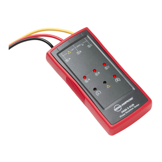
PRM-5-EUR Phase Sequence Tester CONTENTS SYMBOL ......................3 SAFETY INFORMATION ..................3 UNPACKING AND INSPECTION .................4 USING PHASE ROTARY TESTER .................5 Determine the Rotary Field Direction ............5 SPECIFICATIONS ....................6 MAINTENANCE ....................7 Cleaning ......................7... - Page 4 PRM-5-EUR Phase Rotation Tester Indicator for L1 (A), L2 (B), L3 (C) Indicator for false input voltage Indicator for counter-clockwise rotation Indicator for clockwise rotation Test lead input connectors (black / L1, red / L2, yellow / L3) Probe tip cap (black, red, yellow)
-
Page 5: Symbol
SYMBOLS Caution! Risk of electric shock. Caution! Refer to the explanation in this manual. The equipment is protected by double insulation or reinforced insulation Earth (Ground) Measurement category IV (CAT IV) is for measurement performed at the source of the low-voltage installation. CAT IV Examples are electricity meters and measurement on primary overcurrent protection device and ripple control units. -
Page 6: Unpacking And Inspection
• Measurements can be adversely affected by impedances of additional operating circuits connected in parallel or by transient currents. • Do not use the PRM-5-EUR with any of the parts removed. • Do not use the product around explosive gas, vapor, or in damp or wet environments. -
Page 7: Using Phase Rotary Tester
L1, L2, or L3. Refer to Figure 1 for more information about what appears on the back of the PRM-5-EUR . DISPLAY CORRECT FALSE L1 MISSING L2 MISSING L3 MISSING ONE INPUT CONNECTED TO N OR PE Figure 1: Phase indication table (also printed on the back of the PRM-5-EUR) -
Page 8: Specifications
SPECIFICATIONS Determine Rotary Field Direction 3 phase indication Via LEDs Indication of phase rotation Via LEDs Voltage range (Ume) 100…700 V AC phase to phase Frequency range (fn) 16…400 Hz Indicaton for false input voltage difference of > ±30% between the phase to phase voltages (>... -
Page 9: Maintenance
MAINTENANCE Caution To prevent damage to the PRM-5-EUR: • Do not attempt to repair or service the PRM-5-EUR unless qualified to do so. • Make sure that the relevant calibration, performance test, and service information is being used. • Do not use abrasives or solvents. Abrasives or solvents will damage the PRM-5-EUR case.
Need help?
Do you have a question about the PRM-5-EUR and is the answer not in the manual?
Questions and answers