Table of Contents
Advertisement
Advertisement
Table of Contents

Related Manuals for Beha-Amprobe ProInstall-75


Summary of Contents for Beha-Amprobe ProInstall-75
- Page 1 Multifunction Installation Tester ProInstall-75 User Manual...
- Page 3 Multifunction Installation Tester ProInstall-75 User Manual 1/2017, Rev A ©2017 Beha-Amprobe. All rights reserved.
- Page 4 Resellers are not authorized to extend any other warranty on the behalf of Beha-Amprobe. To obtain service during the warranty period, return the product with proof of purchase to an authorized Beha-Amprobe Service Center or to an Beha-Amprobe dealer or distributor.
-
Page 5: Table Of Contents
ProInstall-75 CONTENTS INTRODUCTION ......................3 SYMBOLS ........................3 SAFETY INFORMATION ....................4 UNPACKING THE TESTER ....................5 OPERATING THE TESTER .....................5 Using the Rotary Switch ......................5 Understanding the Pushbuttons ................... 5 Understanding the Display ....................7 Input Terminals ........................9 Error Codes ..........................9 Power-On Options ......................... - Page 6 Continuity (R ) ........................26 Loop Tests (Z ) ........................26 RCD/FI Tests ( T, I N) ......................27 AC Voltage Measurement (V) ....................28 Continuity Testing (R ) ......................28 Insulation Resistance Measurement (R ) ................28 No Trip and Hi Current Modes RCD/FI .................. 29 Prospective Short Circuit Current Test (PSC/I Prospective Earth Fault Current (PEFC) ................
-
Page 7: Introduction
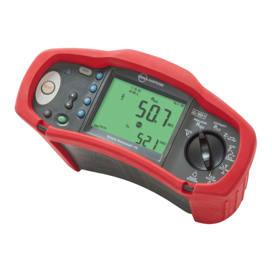
INTRODUCTION The Beha-Amprobe Model ProInstall-75 is a battery powered multifunction installation tester. This tester is designed to measure and test the following: • Voltage and Frequency • Insulation Resistance (EN61557-2) • Continuity (EN61557-4) • Loop/Line Resistance (EN61557-3) • Residual Current Devices (RCD) Tripping Time (EN61557-6) •... -
Page 8: Safety Information
SAFETY INFORMATION A Warning identifies hazardous conditions and actions that could cause bodily harm or death. A Caution identifies conditions and actions that could damage the installation tester or cause permanent loss of data. W Warnings: Read Before Using To prevent possible electrical shock, fire, or personal injury: •... -
Page 9: Unpacking The Tester
UNPACKING AND INSPECTION Your shipping carton should include: • ProInstall-75 • Test lead set • ProInstall-TL-UK (LC38 AMP-MFT, mains test cord) • Alligator clips • Test probe • ProInstall-TL-KIT (Remote test probe and probe tips) • ProInstall-CC (Soft case with carrying strap) •... - Page 10 Number Measurement Function Starts the selected test. The TEST key is surrounded by a “touch pad”. The touch pad measures the potential between the operator and the tester’s PE terminal. If you exceed a 100 V threshold, the W symbol above the touch pad is illuminated. Set RCD variable trip current.
-
Page 11: Understanding The Display
Understanding the Display Number Description Configuration options. Settings you can make within the measurement functions. For example, in the RCD Tripping Time function ( T) you can press F2 to multiply the test current by x1/2, x1, x5 and you can press F3 to select the type of RCD you are testing. - Page 12 Indicates the preset fault voltage limit. The default setting is 50 V. Some locations require the fault voltage be set to 25 V, as specified by local electrical codes. Press F4 when you turn on the tester to toggle the fault voltage between 25 V and 50 V.
-
Page 13: Input Terminals
Figure 1. Error Display Error Condition Code Solution Self-test Fails Return the tester to your distributor or Beha-Amprobe. Over-temp Wait while the tester cools down. Check the installation, in particular, the voltage Fault Voltage between N and PE. -
Page 14: Power-On Options
Power-On Options To select a power-on option, press and the function key simultaneously and then release button. Power-on options are retained when the tester is turned OFF. See Table below. UK - Mode Selected Automatic Lead Swapping Mode Selected Figure 2. Lead Swapping Modes Keys Power-on Options Loop/Line Impedance I... -
Page 15: Making Measurements
MAKING MEASUREMENTS Measuring Volts and Frequency Figure 3. Volts Display/Switch and Terminal Settings To measure voltage and frequency: 1. Turn the rotary switch to the V position. 2. Use two (red and blue) terminals for this test. You can use test leads or mains cord when measuring AC voltage. -
Page 16: Measuring Continuity
Measuring Continuity Figure 5. Continuity Zero Display/Switch and Terminal Settings A continuity test is used to verify the integrity of connections by making a high resolution resistance measurement. This is especially important for checking Protective Earth connections. Note: In countries where electrical circuits are laid out in a ring, it is recommended that you make an end-to-end check of the ring at the electrical panel. -
Page 17: Loop Impedance (Line To Protective Earth L-Pe)
Loop Impedance (Line to Protective Earth L-PE) Loop impedance is source impedance measured between Line (L) and Protective Earth (PE). You can also ascertain the Prospective Earth Fault Current (PEFC) that is the current that could potentially flow if the phase conductor is shorted to the protective earth conductor. The tester calculates the PEFC by dividing the measured mains voltage by the loop impedance. -
Page 18: Earth Resistance Testing By Loop Method
6. Press and release . Wait for the test to complete. The primary (upper) display shows the loop impedance. 7. To read the Prospective Earth Fault Current, press the key and select lK. The Prospective Earth Fault Current appears in amps or kilo amps in the secondary (lower) display. -
Page 19: Line Impedance
2. Press to select L-PE. 3. Press to select RE (resistance). 4. Press and release . Wait for the test to complete. • The primary (upper) display shows the loop impedance. • The secondary (lower) display shows the earth resistance. Line Impedance Line impedance is source impedance measured between Line conductors or Line and Neutral. -
Page 20: Measuring Rcd Tripping Time
WWarning At this step, be careful not to select L-PE because a high current loop test will take place. Any RCDs in the system will trip if you proceed. Note: Connect the leads in a single-phase test to the system line and neutral. To measure line-to-line impedance in a 3-phase system, connect the leads to 2 phases. - Page 21 WWarning • Test the connection between the N-conductor and earth before starting the test. A voltage between the N-conductor and earth may influence the test. • Leakage currents in the circuit following the residual current protection device may influence measurements. •...
-
Page 22: Measuring Rcd Tripping Current
To measure RCD tripping time using Auto mode: 1. Plug the tester into the outlet. 2. Turn the rotary switch to the position. 3. Press F1 to select the RCD current rating (10, 30, or 100 mA). 4. Press F2 to select Auto mode. 5. - Page 23 WWarning • Test the connection between the N-conductor and earth before starting the test. A voltage between the N-conductor and earth may influence the test. • Leakage currents in the circuit following the residual current protection device may influence measurements. •...
-
Page 24: Rcd Testing In It Systems
RCD testing in IT systems RCD testing at locations with IT systems requires a special test procedure because the Protective Earth connection is grounded locally and is not tied directly to the power system. The test is conducted at the electrical panel using probes. Use the connection shown in Figure 13 when performing RCD testing on IT electrical systems. -
Page 25: Maintaining The Tester
To perform a phase sequence test: 1. Turn the rotary switch to the position. 2. The primary (upper) display shows: • 123 for correct phase sequence. • 321 for reversed phase sequence. • Dashes (---) instead of numbers if insufficient voltage is sensed. MAINTAINING THE TESTER Cleaning Periodically wipe the case with a damp cloth and mild detergent. -
Page 26: Testing The Fuse
2. Short the leads and press and hold 3. If the fuse is bad, FUSE or Err1 will appear on the display to indicate the tester is damaged and needs repair. Contact Beha-Amprobe Service for repair (see Contacting Beha-Amprobe). -
Page 27: Detailed Specifications
DETAILED SPECIFICATIONS Features Measurement Function √ Voltage & Frequency √ Wiring polarity checker √ Insulation Resistance √ Loop & Line Resistance √ Prospective Short-Circuit current (PSC/I √ RCD switching time √ ramp test RCD tripping level √ RCD variable current √... -
Page 28: General Specifications
General Specifications Specification Characteristic Size 10 cm (L) x 25 cm (W) x 12.5 cm (H) Weight (with batteries) 1.3 kg Battery size, quantity Type AA, 6 ea. Battery type Alkaline supplied. Usable with 1.2 V NiCd or NiMH batteries (not supplied) Battery life (typical) 200 hours idling Fuse... -
Page 29: Electrical Measurement Specifications
ELECTRICAL MEASUREMENT SPECIFICATIONS The accuracy specification is defined as ±(% reading +digit counts) at 23 °C ±5 °C, ≤80 % RH. Between -10 °C and 18 °C and between 28 °C and 40 °C, accuracy specifications may degrade by 0,1 x (accuracy specification) per °C. The following tables can be used for the determination of maximum or minimum display values considering maximum instrument operating uncertainty per EN61557-1, 5.2.4. -
Page 30: Continuity (Rlo )
Continuity (R Limit Value Maximum Display Limit Value Maximum Display Value Value 0.16 2.68 0.25 3.58 0.34 4.48 0.43 5.38 0.52 6.28 0.61 7.18 8.08 0.79 8.98 0.88 17.98 1.78 26.8 Loop Tests (Z Loop Z Loop Z Loop Z Loop R Hi Current No Trip... -
Page 31: Rcd/Fi Tests ( P T, I P N)
Loop Tests (Z ) (cont.) 1000 1000 RCD/FI Tests (ΔT, IΔN) RCD/FI Time RCD/FI Current Limit Value Maximum Display Value Limit Value Maximum Display Value 18.1 0.43 27.1 0.52 36.1 0.61 45.1 54.1 0.79 63.1 0.88 72.1 1.78 81.1 2.68 90.1 3.58 180.1... -
Page 32: Ac Voltage Measurement (V)
AC Voltage Measurement (V) Range Resolution Accuracy Input Impedance Overload 50 Hz – 60 Hz Protection 500 V 0.1 V 0.8 % + 3 digits 3.3 MΩ 660 V rms Continuity Testing (R Range Resolution Open Circuit Voltage Accuracy (Autoranging) 20 Ω... -
Page 33: No Trip And Hi Current Modes Rcd/Fi
Auto Discharge Discharge time constant <0.5 second for C = 1 μF or less. Live Circuit Detection Inhibits test if terminal voltage >30 V prior to initiation of test. Maximum Capacitive Load Operable with up the 5 μF load. No Trip and Hi Current Modes RCD/FI Mains Input Voltage Range 100 - 500 V ac (50/60 Hz) Input Connection... -
Page 34: Rcd Testing
RCD TESTING RCD Types Tested RCD Type √ √ √ √ Note: [1] AC – Responds to ac [2] G – General, no delay [3] S – Time delay [4] A – Responds to pulsed signal [5] RCD test inhibited for V >265 ac RCD tests permitted only if the selected current, multiplied by earthing resistance, is <50V. -
Page 35: Maximum Trip Time
Measurement Range Current *RCD Type Trip Time Accuracy Multiplier Europe X ½ 310 ms 2000 ms ± (1% Reading + 1ms) X ½ 510 ms 2000 ms ± (1% Reading + 1ms) 310 ms 310 ms ± (1% Reading + 1ms) 510 ms 510 ms ±... -
Page 36: Mains Wiring Test
MAINS WIRING TEST Icons ( ) indicate if L-PE or L-N terminals are reversed. Instrument operation is inhibited and an error code is generated if the input voltage is not between 100 V and 500 V. The UK Loop and RCD tests are inhibited if the L-PE or the L-N terminals are reversed. OPERATING RANGES AND UNCERTAINTIES PER EN 61557 EN 61557 Display... - Page 37 Operating Uncertainties per EN 61557 The Operating Uncertainty shows the maximum possible uncertainty when all influence factors E1-E10 are counted. Intrinsic 0.80 % 1.50 % 10.00 % 6.00 % 1.00 % 5.00 % Uncertainty A Influence Quantity E1 - Position 0.00 % 0.00 % 0.00 %...
- Page 38 Visit beha-amprobe.com for • Catalog • Application notes • Product specifications • User manuals Beha-Amprobe ® In den Engematten 14 79286 Glottertal, Germany Phone: +49 (0) 7684 8009 - 0 beha-amprobe.de Beha-Amprobe ® 52 Hurricane Way Norwich, Norfolk NR6 6JB United Kingdom Phone: +44 (0) 1603 25 6662 beha-amprobe.com...
Need help?
Do you have a question about the ProInstall-75 and is the answer not in the manual?
Questions and answers