Table of Contents
Advertisement
Telaris Multifunction Electrical
Installation Tester Series
Telaris ProInstall-100-EUR
Telaris ProInstall-200-EUR
Telaris ProInstall-100-D
Telaris ProInstall-200-D
Telaris ProInstall-100-CH
Telaris ProInstall-200-CH
Telaris ProInstall-100-DK
Users Manual
7/2013, 6001109 A
©2013 Amprobe Test Tools.
All rights reserved.
Advertisement
Table of Contents

Related Manuals for Beha-Amprobe Telaris ProInstall-100-EUR


Summary of Contents for Beha-Amprobe Telaris ProInstall-100-EUR
- Page 1 Telaris Multifunction Electrical Installation Tester Series Telaris ProInstall-100-EUR Telaris ProInstall-200-EUR Telaris ProInstall-100-D Telaris ProInstall-200-D Telaris ProInstall-100-CH Telaris ProInstall-200-CH Telaris ProInstall-100-DK Users Manual 7/2013, 6001109 A ©2013 Amprobe Test Tools. All rights reserved.
- Page 2 European non-warranty units can be replaced by your Amprobe distributor for a nominal charge. Please check the “Where to Buy” section on www.Amprobe.eu for a list of distributors near you. Amprobe Europe* Beha-Amprobe In den Engematten 14 79286 Glottertal, Germany Tel.: +49 (0) 7684 8009 - 0 www.Amprobe.eu...
-
Page 3: Table Of Contents
Telaris ProInstall-100 / Telaris ProInstall-200 CONTENTS INTRODUCTION ........................ 4 SAFETY ..........................4 UNPACKING THE TESTER ....................5 OPERATING THE TESTER ....................6 Using the Rotary Switch ......................6 Understanding the Pushbuttons ................... 7 Understanding the Display ....................8 Input Terminals ........................9 Using the IR Port ........................ - Page 4 Testing the Fuse ........................25 DETAILED SPECIFICATIONS ..................25 Features by Model ......................... 25 General Specifications ......................26 ELECTRICAL MEASUREMENT SPECIFICATIONS ............27 Continuity (RLO) ........................27 Insulation Resistance (RISO) ....................27 No Trip and Hi Current Modes RCD/FI .................. 28 Prospective Short Circuit Current Test (PSC/IK) ..............29 RCD TESTING ........................29 RCD Types Tested ........................
-
Page 5: Introduction
INTRODUCTION The Amprobe Model Telaris ProInstall-100 and Telaris ProInstall-200 are battery powered electrical installation testers. This manual applies to all models. All figures show the Model Telaris ProInstall-200. These testers are designed to measure and test the following: • Voltage and Frequency • Insulation Resistance (EN61557-2) • Continuity (EN61557-4) • Loop/Line Resistance (EN61557-3) - Page 6 • Do not use the product around explosive gas, vapor or in damp or wet environments. • Do not use test leads if they are damaged. Examine the test leads for damaged insulation, exposed metal, or if the wear indicator shows. Check test lead continuity. • Use only current probes, test leads, and adapters supplied with the product.
-
Page 7: Operating The Tester
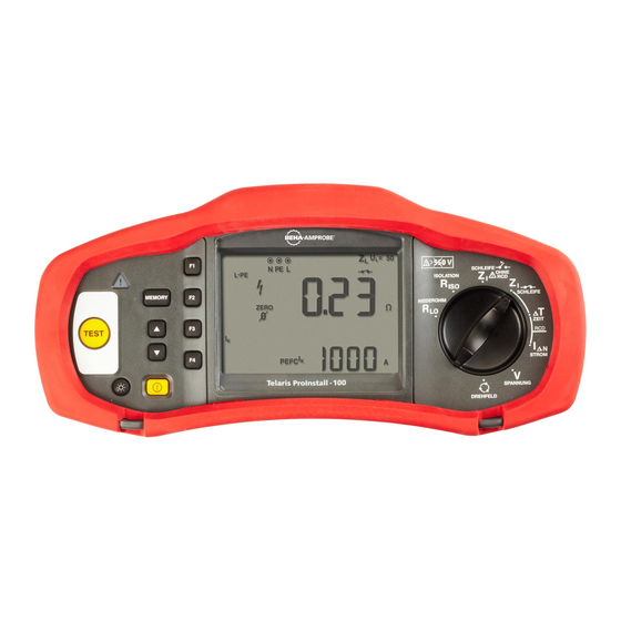
OPERATING THE TESTER Using the Rotary Switch Use the rotary switch (Figure 1 and Table 4) to select the type of test you want to perform. Understanding the Pushbuttons Use the rotary switch to select the type of test you want to perform.Use the pushbuttons to control operation of the tester, select test results for viewing, and scroll through selected test results. -
Page 8: Understanding The Display
Continuity. Insulation resistance. Loop impedance — Hi current trip mode Loop impedance — No trip mode. RCD tripping time. RCD tripping level. Volts Phase rotation. Earth resistance. Rotary switch. Understanding the Display Comp 34 33 Number Descri ption Displays the selected Memory mode. Memory modes are: Select (F1), Store (F2), Recall (F3), or Clear (F4). - Page 9 Indicates the selected rotary switch setting. The measurement value in the primary display also corresponds to the switch setting. Rotary switch settings are: Insulation RCD trip time Continuity RCD trip current Loop no trip Earth Loop hi current trip Phase Rotation Indicates the preset fault voltage limit.
-
Page 10: Input Terminals
Input Terminals Use the rotary switch to select the type of test you want to perform. Number Descri ption L (Line) PE (Protective Earth) N (Neutral) Using the IR Port The Model Telaris ProInstall-100 and Telaris ProInstall-200 have an IR (infrared) port, see Figure 23, which allows you to connect the tester to a computer and upload test data using a Amprobe PC software. -
Page 11: Power-On Options
Over-temp Wait while the tester cools down. Check the installation, in particular, the voltage Fault Voltage between N and PE. Put the stakes deeper into the soil. Tamp down the soil Excessive Probe directly around the stakes. Pour water around the stakes Resistance but not at the earth ground under test. -
Page 12: Making Measurements
MAKING MEASUREMENTS Measuring Volts and Frequency Figure 8. Volts Display/Switch and Terminal Settings To measure voltage and frequency: 1. Turn the rotary switch to the V position. 2. Use all (red, blue, and green) terminals for this test. You can use test leads or mains cord when measuring AC voltage. -
Page 13: Measuring Continuity
Measuring Continuity Figure 10. Continuity Zero Display/Switch and Terminal Settings A continuity test is used to verify the integrity of connections by making a high resolution resistance measurement. This is especially important for checking Protective Earth connections. Note: In countries where electrical circuits are laid out in a ring, it is recommended that you make an end-to-end check of the ring at the electrical panel. -
Page 14: Loop Impedance (Line To Protective Earth L-Pe)
Loop Impedance (Line to Protective Earth L-PE) Loop impedance is source impedance measured between Line (L) and Protective Earth (PE). You can also ascertain the Prospective Earth Fault Current (PSC) that is the current that could potentially flow if the phase conductor is shorted to the protective earth conductor. The tester calculates the PSC by dividing the measured mains voltage by the loop impedance. -
Page 15: Line Impedance
To measure loop impedance—Hi current tri p mode: If no RCDs are present in the system under test, you can use the high current Line Earth (L- PE) loop impedance test. 1. Turn the rotary switch to the position. 2. Connect all three leads to the L, PE, and N (red, green, and blue) terminals of the tester. Only the calibrated test lead which are in scope of supply must be used! The resistance of the calibrated test leads is subtracted from the result automatically. -
Page 16: Measuring Rcd Tripping Time
WWarning At this step, be careful not to select L-PE because a high current loop test will take place. Any RCDs in the system will tri p if you proceed. Note: Connect the leads in a single-phase test to the system live and neutral. To measure line-to-line impedance in a 3-phase system, connect the leads to 2 phases. - Page 17 WWarning • Leakage currents in the circuit following the residual current protection device may influence measurements. • The displayed fault voltage relates to the rated residual current of the RCD. • Potential fields of other earthing installations may influence the measurement. •...
-
Page 18: Measuring Rcd Tripping Current
To measure RCD tri pping time using Auto mode: 1. Plug the tester into the outlet. 2. Turn the rotary switch to the position. 3. Press F1 to select the RCD current rating (10, 30, or 100 mA). 4. Press F2 to select Auto mode. 5. -
Page 19: Rcd Testing In It Systems
This test measures the RCD tripping current by applying a test current and then gradually increasing the current until the RCD trips. You can use the test leads or mains cord for this test. A 3 wire connection is required for testing of RCD type B. WWarning •... -
Page 20: Measuring Earth Resistance
Mains Supply PE (L2/Green) N (L3/Blue) L (L1/Red) Figure 18. Connection for RCD Testing on IT Electrical Systems The test current flows through the upper side of the RCD, into the L terminal, and returns though the PE terminal. Measuring Earth Resistance Figure 19. -
Page 21: Testing Phase Sequence
To measure earth resistance: 1. Turn the rotary switch to the position. 2. Press and release . Wait for the test to complete. • The primary (upper) display shows the earth resistance reading. • Voltage detected between the test rods will be displayed in the secondary display. If greater than 10 V, the test is inhibited. -
Page 22: Memory Mode
Memory mode You can store measurements on the tester: • Telaris ProInstall-100 – up to 399 • Telaris ProInstall-200 – up to 1399 The information stored for each measurement consists of the test function and all user selectable test conditions. Data for each measurement is assigned a data set number, data subset number, and a data id number. -
Page 23: Recalling A Measurement
• If the memory is not full, the data will be saved, the tester will automatically exit Memory mode and the display will revert back to the previous test mode. • If the data identity has been previously used, the display will show STO? Press F2 again to store the data, press F1 to choose another data identity, press exit Memory mode. -
Page 24: Maintaining The Tester
To upload test results: 1. Connect the IR serial cable to the serial port on the PC. 2. Attach the IR adapter and the device to the tester as shown in Figure 23. 3. Start the Amprobe PC software program. 4. -
Page 25: Testing The Fuse
5. Replace the batteries and the battery door. Note: All stored data will be lost if the batteries are not replaced within approximately one minute 6. Secure the door by turning the screws one-quarter turn clockwise. Figure 24. Replacing the Batteries Testing the Fuse 1. -
Page 26: Detailed Specifications
DETAILED SPECIFICATIONS Features Measurement Function Telaris ProInstall-100 Telaris ProInstall-200 Voltage & Frequency √ √ Wiring polarity checker √ √ Insulation Resistance √ √ Loop & Line Resistance √ √ Prospective Short-Circuit current √ √ (PSC/IK) RCD switching time √ √ RCD tripping level √... -
Page 27: Continuity (Rlo)
Complies with EN61010-1 Ed 3. Safety Overvoltage Category: 500 V/CAT III 300 V/CAT IV Measurement Category III is for measurements performed in the building installation. Examples are distribution panels, circuit breakers, wiring and cabling. Category IV equipment is designed to protect against transients from the primary supply level, such as an electrical meter or an overhead or underground utility service. -
Page 28: Insulation Resistance (Riso)
Press the F3 to compensate the test probe. Test Probe Zeroing Can subtract up to 2 Ω of lead resistance. Error message for >2 Ω. Live Circuit Detection Inhibits test if terminal voltage >10 V ac detected prior to initiation of test. Insulation Resistance Measurement (R 100-250-500-1000 V Test Voltages... -
Page 29: Prospective Short Circuit Current Test (Psc/Ik)
Range Resolution Accuracy 20 Ω 0.01 Ω No Trip mode: ±(4 % + 6 digits) Hi Current mode: ±(3 % + 4 digits) 200 Ω 0.1 Ω ±(5 %) 2000 Ω 1 Ω ±6 % Note: [1] Valid for resistance of neutral circuit <20 Ω and up to a system phase angle of 30 °. [2] Valid for mains voltage >200 V. -
Page 30: Test Signals
Test Signals RCD Type Test Signal Descri ption The waveform is a sinewave starting at zero crossing, polarity (sinusoidal) determined by phase selection (0 ° phase starts with low to high zero crossing, 180 ° phase starts with high to low zero crossing). -
Page 31: Maximum Trip Time
Maximum Tri p Time Tri p Time Limits AC G, A, B Less than 300 ms AC G-S, A-S, B-S Between 130 ms and 500 ms AC G, A, B Less than 40 ms AC G-S, A-S, B-S Between 50 ms and 150 ms RCD/FI-Tri pping Current Measurement/Ramp Test ( Measurement Range Measurement... -
Page 32: Phase Sequence Indication
Phase Sequence Indication Icon icon Phase Sequence indicator is active. Display of Phase Sequence Displays “1-2-3” in digital display field for correct sequence. Displays “3-2-1” for incorrect phase. Dashes in place of a number indicate a valid determination could not be made. 100 to 500 V Mains Input Voltage Range (phase-tophase) - Page 33 • Catalog • Application notes • Product specifications • User manuals Amprobe ® www.Amprobe.com info@amprobe.com Everett, WA 98203 Tel: 877-AMPROBE (267-7623) Amprobe Europe ® Beha-Amprobe In den Engematten 14 79286 Glottertal, Germany Please Tel.: +49 (0) 7684 8009 - 0 Recycle...
Need help?
Do you have a question about the Telaris ProInstall-100-EUR and is the answer not in the manual?
Questions and answers