Table of Contents
Advertisement
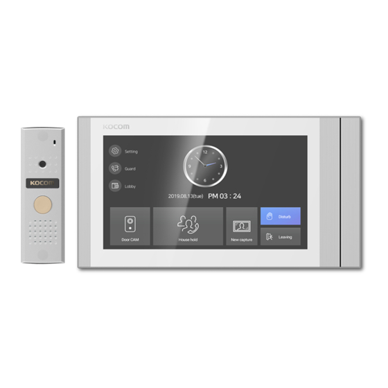
KCV-T701SM MANUAL
GUI Full Touch Videophone
7" Digital LCD Screen (NTSC/PAL)
●
Simple and Convenient UI & Full Capacitvive screen
●
Compatible with 1080p (FHD) AHD CCTV
●
(TVI, AHD, CVI)
Auto still image capture (Max 32 cuts) Door Camera
●
[7" Digital Color LCD Videophone]
AHD CCTV Compatible
Connection up to 2 Door Cameras and
●
4 Monitors with Sub-interphone (KIP-32G)
Overall or individual calling available
●
Multifamily, Apartment application
●
(KLP-C420 SYSTEM)
www.kocom.com
Advertisement
Table of Contents

Related Manuals for KOCOM KCV-T701SM


Summary of Contents for KOCOM KCV-T701SM
- Page 1 KCV-T701SM MANUAL [7" Digital Color LCD Videophone] AHD CCTV Compatible GUI Full Touch Videophone 7" Digital LCD Screen (NTSC/PAL) Connection up to 2 Door Cameras and ● ● Simple and Convenient UI & Full Capacitvive screen 4 Monitors with Sub-interphone (KIP-32G) ●...
-
Page 2: Cautions For Safety
Cautions for safety For safe use, please stick to the following cautions. ·Please do not dispose this manual after reading the instructions carefully. ·Please read all instructions to set up rightly. ·This Cautions for Safety may include items that are not contained in specifications of the product that consumer purchases. The important marks in the manual. -
Page 3: Cautions For Use
Safety Instructions, Warnings and Cautions of Each System ·Do not disassemble this unit at will as this device is composed by precision parts. 쪾 ·Install the unit by following the set-up instructions of Kocom. ·Do not touch or insert any foreign substances, for example, sticker, magnetic, opener and the like. -
Page 4: Installation Location
Installation Location ■ Monitor installation location ■ Camera installation location ·Recommended installation ·Recommended installation height is about 1,500mm height of door camera is where screen center is at where lens is about 1,400mm eye level. In this case, above the floor. In this case, wall - hanging metal center camera stack center (Buried (center of piping) is 1,450mm... -
Page 5: Components Of Product
70(W) x 125(H) x 21(D) 40(W) x 120(H) x 22(D) Viewing angle Diagonal 90˚ Adjusting Angle ※ Door Camera Wiring : Polarzied 4 wire(VCC[12V] / GND / AUDIO / VIDEO) ※ Recommend adaptor : CT-140200 (14V) / UT60-140210-6-02(14V) ※ Kocom is not responsible of non verified power supply. -
Page 6: Name And Functions Of Each Part
Name and Functions of Each Part ■ Monitor part ·Front ·Up side ·Back ① 7" Touch LCD Montior with touch screen ② Microphone ③ DC Power ON/OFF Switch ④ Speaker ⑤ Terminal : Ports for Door camera1,2, Interphone, Door open, Inner data ■... -
Page 7: Product Wiring Diagram
Product Wiring Diagram ■Camera mode diagram Maximum wiring distance : 100m(D1(0.41M) Camera, IN-OUT wiring must be done.) 50m(2M Camera, IN-OUT wiring must be done.) (UTP CAT5e) *Refer to "Product wiring" below for cable wiring The monitor that is installed furthest from the camera should be set to Last device. - Page 8 Product Wiring Diagram ■2M Door camera VCC(DC12V) - Orange GND - W/Orange, W/Green, W/Brown, Brown VOICE - Green VIDEO - Blue, W/Blue ④ ① KIP-32G BACK VIEW ① ④ A. CAMERA 1 C. INTERPHONE KC-S81M(D1) ① CA1 VCC ① INTER VCC BACK VIEW ②...
- Page 9 Product Wiring Diagram ■D1(0.41M) Door Camera ④ ① KIP-32G BACK VIEW ① ④ A. CAMERA 1 C. INTERPHONE KC-S81M(D1) ① CA1 VCC ① INTER VCC BACK VIEW ② CA1 GND ② INTER GND ③ CA1 AUDIO ③ INTER AUDIO ④ CA1 VIDEO ④...
- Page 10 ADAPTOR KIP-32G KIP-32G KIP-32G KIP-32G Product Wiring Diagram ■CCTV mode diagram Maximum wiring distance : 100m(D1(0.41M) Camera, IN-OUT wiring must be done.) 50m(2M Camera, IN-OUT wiring must be done.) (UTP CAT5e) *Refer to "Product wiring" below for cable wiring Coaxial cable should be used for CCTV connection. The monitor that is installed furthest from the camera should be set to Last device.
- Page 11 Product Wiring ■ Door camera connection (1:1) Outdoor Camera Indoor Monitor ⑤⑥ ④ ③ ② ① DC Door Lock ORANGE ORANGE ①COM(BLACK) ①VCC(BLUE) ①CA1 VCC ①CA2 VCC W/Orange W/Orange ②NO(BROWN) W/Brown W/Brown Brown Brown External Power ②GND(YELLOW) ②CA1 GND ②CA2 VCC ③NC(ORANGE) W/Green W/Green...
- Page 12 Product Wiring Diagram ■ CAM1 - Outdoor Camera, CAM2 - 420System Connection (Ex-monitor Connection) Indoor monitor Ex-Indoor monitor CAM1 : Door camera CAMERA 1 CAMERA 1 ORANGE ORANGE ORANGE ①VCC(BLUE) ①CA1 VCC ①CA1 VCC W/Orange W/Orange W/Orange ②GND(YELLOW) ②CA1 GND ②CA1 GND W/Green W/Green...
- Page 13 Product Wiring ■ CAM1 - CCTV, CAM2 - 420system Connection (Ex-indoor monitor Connection) Indoor monitor Ex-Indoor monitor CAM1 : CCTV ORANGE W/ORANGE W/BROWN BROWN W/GREEN GREEN ORANGE ORANGE CAMERA 1 CAMERA 1 CCT V W/BLUE W/ORANGE W/ORANGE ①CA1 VCC ①CA1 VCC BLUE W/BROWN W/BROWN...
- Page 14 Product Wiring ■Correct wiring The monitor that is installed furthest from the camera should be set to Last device. Refer to the page 20 for setting and the rest other monitors except the one chosen as "Last device" must be set as "X" DEVICE 1 DEVICE 2 DEVICE 3...
- Page 15 Product Wiring ■CCTV Camera connection (CAMERA 1,2 Port) (How to Connect when using coaxial cable) MONITOR CA1 or CA2 CCTV CAMERA CCTV GND ① CA1 or 2 VCC ② CA1 or 2 GND ③ CA1 or 2 AUDIO CCTV VIDEO IN-OUT WIRING (X) Coaxial Cable ④...
- Page 16 KCV-T701SM How to Operate ※Cautions Before Using the Device Please follow following steps before using the device. 1. DEVICE ID - When extending additional monitors, each ID must be set. ID collision may cause malfunction. - In case of ID Collision, "ID collision" may be shown at the top of its screen.
- Page 17 Power ON - Before turning the devices on, all connection (door cameras, extension monitors, etc) must be fully made. - As you turn on the power switch placed at the top of its device, and you will find booting progress and the home screen afterward in order.
- Page 18 Home Screen Setting - Home screen is the start screen where all functions of the product can be run. - Press menu icon in Home screen to run desired functions. Home screen UI ① Icon for Setting Screen : ⑦ Icon for Preventing Disturbances : Button to function all of the calling melody Menu setting in silence...
- Page 19 Calling From Outdoor Camera When calling from the outdoor camera, you can see the image of visitors, make a call, and open the door. ▶ ▶ Press the call button When calling to the monitor, you will see When pressing OFF button while talking with to make a call.
- Page 20 Monitoring Outdoor Camera ▶ ▶ When pressing the outdoor camera While the image of outdoor camera Press off button then calling gets monitoring button, the image from #1 is on, press "CAM2" then you see finished. the outdoor CAM 1 will be shown. the other image.
- Page 21 Extension Calling & Receiving Function In case of extended monitors or interphones, you can perform extension calling. To perform extension calling, you MUST set each device's numbering at the "Setting" From ID #1 to #4 is available to register, you MUST register in order. ▶...
- Page 22 Calling From The Lobby ▶ When calling from the lobby, calling melody will be Pressing door opening button during talk status, then rung. Then, the image at the lobby will be displayed. the lobby's door gets opened and calling will be off. Press door opening button and lobby's door gets Press off button and the talk will be off.
- Page 23 Lobby Monitoring KLP-C420 firmware more than 03.00 ver, KVS-A8P/A4P firmware more than 03.00 ver are available ▶ Press lobby button from the home screen, then lobby When pressing door open button during monitoring can be monitored. status, the lobby door's gets opened and calling gets off right away.
- Page 24 QR Code ▶ Press Help button from the home screen, Take a QR code and check the manual. Manual QR code appears. Following Points are Normal Operating Condition, NOT a Quality Failure ① When connected monitor is in talk status, KIP-32G the sub interphone gets connected when you pick up the handset. (It means the sub interphone can hear and join into the communication) ②...
- Page 25 Setting Menu Screen Home screen > By pressing setting button, it will move to setting menu screen. ① General ② Sound Device ID : Setting monitor's ID. Sound item : Cam1, Cam2, Lobby, Guard, Device, Interphone Time Setting : System time setting. Calling volume : 1~9 Date Setting : System date setting.
-
Page 26: Auto Capture
Your usage of this mode could lead to shortened life time of product. There might be possible afterimage on display due to continuously actived display. We, Kocom, is not resoponsible for possible problem due to this mode and usage. Auto capture : When you select "ON", automatic screen capture... -
Page 28: Warranty Card
2) If this product breaks down during proper use as a result of product defect, KOCOM will repair it within one year from date of purchase free of charge. 3) The following cases will be subject to charge, even during warranty period: a.
Need help?
Do you have a question about the KCV-T701SM and is the answer not in the manual?
Questions and answers