Table of Contents
Advertisement
Advertisement
Table of Contents

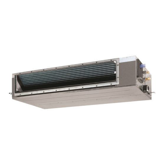
Summary of Contents for Daikin FDMF48AVMK
- Page 1 FDMF48AVMK RZF48AYMK FDMF54AVMK RZF54AYMK 3P640554-1-KA...
- Page 2 FDMF48AVMK , FDMF54AVMK a certain product or domain. against unsafe practices.
- Page 6 48-54 48,54 1500 1538 1800...
- Page 8 PART Dia at AA Dia at AB Table ø 9.52 X t0.8 ø 12.7 X t 1mm Installtion kit auxiliary pipe. ø 15.9 X t1.0 ø 22.2 X t1 mm Installtion pipe size ø 9.52 12.7 12.7 ø 15.9 22.2 22.2 Installtion kit Flare End...
- Page 20 RZF48AYMK, RZF54AYMK # Safety Precaution ..........................19-21 ....................... 1 About the documentation ..........................2 About the box ............................3 Preparation ............................22-31 4 Installation ..........................31-32 5 Commissioning ..........................6 Disposal ..........................7 Technical data 6 Piping Diagram ..........................7 Existing piping reuse ........................
-
Page 22: About The Documentation
The original documentation is written in English. All other languages are translations. Technical engineering data ▪ A subset of the latest technical data is available on the regional Daikin website (publicly accessible). ▪ The full set of latest technical data is available on the Daikin Business Portal (authentication required). -
Page 23: Preparing The Installation Site
Preparation NOTICE Fix the outdoor unit to the foundation bolts using nuts with resin washers (a). If the coating on the fastening area is Preparing the installation site stripped off, the metal can rust easily. WARNING The appliance shall be stored in a room without continuously operating ignition sources (example: open 4.1.2 To install the outdoor unit... -
Page 24: Connecting The Refrigerant Piping
Distance between anchor points Bottom frame Drain holes Knockout hole for snow Snow In regions with snowfall, snow might build up and freeze between the heat exchanger and the casing of the unit. This might decrease the operating efficiency. To prevent this: 1 Remove the beam structure (see figure below). -
Page 25: Checking The Refrigerant Piping
NOTICE NOTICE Precautions when making knockout holes: Do not block the air vents. This could affect air circulation inside the unit. ▪ Avoid damaging the casing and underlying piping. ▪ After making the knockout holes, we recommend to remove the burrs and paint the edges and areas around the edges using repair paint to prevent rusting. -
Page 26: Charging Refrigerant
Charging additional refrigerant NOTICE Before charging additional refrigerant, make sure the outdoor unit's Make sure to use a recommended bubble test solution external refrigerant piping is checked (leak test, vacuum drying). from your wholesaler. Do not use soap water, which may cause cracking of flare nuts (soap water may contain salt, INFORMATION which absorbs moisture that will freeze when the piping... -
Page 27: Precautions When Charging Refrigerant
Location of service ports: 4.4.3 Precautions when charging refrigerant INFORMATION Also read the precautions and requirements in the following chapters: ▪ General safety precautions ▪ Preparation 4.4.4 Definitions: L1, H1 Pair Internal service port Stop valve with service port (liquid) Stop valve with service port (gas) Typical workflow –... - Page 28 To determine the additional refrigerant amount (R in kg) (in case of pair) 1 When the unit is powered on and not running, hold down the Standard piping size BS1 pushbutton for 5 seconds. L1 (m) Result: You will reach the setting mode, the 7 segment display will show '2 0 0'.
-
Page 29: Connecting The Electrical Wiring
4.4.7 To fix the fluorinated greenhouse gases NOTICE label ▪ Follow the wiring diagram (delivered with the unit, 1 Fill in the label as follows: located at the inside of the service cover). Contains fluorinated greenhouse gases ▪ Make sure the electrical wiring does NOT obstruct RXXX proper reattachment of the service cover. - Page 30 Cable tie 3N~ 50/60 Hz 3 Fix the cables (power supply and interconnection cable) with a 380-415 V cable tie to the stop valve attachment plate and route the wiring L1 L2 L3 according to the illustration above. 4 Choose a knockout hole and remove the knockout hole by tapping on the attachment points with a flat head screwdriver and a hammer.
-
Page 31: Finishing The Outdoor Unit Installation
This data can be found in the installer reference guide Open the liquid stop valve and gas stop valve by or via the Daikin website. removing the cap and turning counterclockwise with a hex wrench until it stops. -
Page 32: Error Codes When Performing A Test Run
Action Result Error codes when performing a Press at least 4 seconds. The Service Settings menu test run is displayed. If the installation of the outdoor unit has NOT been done correctly, the following error codes may be displayed on the user interface: Select Test Operation. -
Page 33: Service Space: Outdoor Unit
Service space: Outdoor unit Suction side In the illustrations below, the service space at the suction side is based on 35°C DB and cooling operation. Foresee more space in the following cases: ▪ When the suction side temperature regularly exceeds this temperature. ▪... - Page 35 FDMF48AVMK RZF48AYMK FDMF54AVMK RZF54AYMK...
- Page 40 RZF48AYMK RZF54AYMK...
- Page 48 • The manufacturer reserves the right to revise any of the specification and design contain herein at any time without prior notification. DAIKIN MIDDLE EAST & AFRICA FZE P.O. Box 18674, Jebel Ali Free Zone, Dubai, UAE, Tel: +971 (0) 4 815 9300, Fax: +971 (0) 4 815 9311 Email: info@daikinmea.com Web: www.daikinmea.com...
- Page 51 3P640554-1-KB...
- Page 96 DAIKIN Y '-9 �J � J\ J '-9 J J J 'i t � � J , J 'iJ J u:'.)l, p� I (c,!I.JA c.9� ..l.JJA uL,. �) w..JJ�J 34-01....'4_jill J.il� � I J <.,r..Jt.i:,,. 44-35....�\ J.il� RZF30AVMK FDMF30AVMK �...


Need help?
Do you have a question about the FDMF48AVMK and is the answer not in the manual?
Questions and answers