Table of Contents
Advertisement
Quick Links
Advertisement
Table of Contents

Related Manuals for Rangevision SPECTRUM


Summary of Contents for Rangevision SPECTRUM
- Page 1 RANGEVISION Setup and calibration SPECTRUM...
-
Page 2: Table Of Contents
Contents Contents Introduction Technical specifications 3D resolution System requirements Preparing for work Package contents Installing software and drivers Setting up your computer for work with the scanner Connecting projector Configuring computer parameters Scanner Assembly Scanner setup ScanCenter NG launch Select scanning zone Calibration field parameters Placing the calibration plate Initial setup of cameras and lenses Checking camera arrangement Finding a working distance Adjustment of the projector focus Bringing the cameras together Final calibration of the cameras Calibrating the scanner Calibration plate Full calibration Fast calibration (orientation) Focus assessment during calibration... -
Page 3: Introduction
Introduction Thank you for choosing RаngeVisiоn Spectrum! Please read this manual before using RangeVision 3D scanner. Here are described the procedures for preparing the scanner, installing the required drivers, calibration procedure, scanning procedure, and tips for acquiring high-quality three-dimensional object model. Information may be amended from time to time. These changes will be inserted into the new versions of the manual, or in the additional documents and publications. -
Page 4: Technical Specifications
Technical specifications Scanning zone Scanning Area (WxHxD) (mm) 520*400*400 320*250*220 120*90*100 3D point accuracy 0.12 mm 0.06 mm 0.04 mm Model Spectrum Resolution of cameras 3 Mpix Diagonal of the matrix 1/2” Texture scanning 3D resolution Scanning zone 3D resolution 0.25 mm 0.15 mm 0.06 mm Operation distance 1.05 m 0.6 m 0.3 m System requirements operating system - Windows 7/8/10 64bit, ● ● processor - Intel Core i3/i5 1.8 GHz and better, ● graphics card with HDMI output, ● RAM - Not less than 8 GB, 3 USB-ports. -
Page 5: Preparing For Work
Preparing for work Package contents RаngeVisiоn 3D scanner is supplied in a protected road hard case. Camera tripod is placed in a separate bag. The scanner is equipped with three scanning areas. Scanning area is a calibration plate and stand for the calibration plate. - Page 6 № Name qty. Scanning module: Installation construction with projector Cable kit for connection to a PC (2 USB + HDMI) Machine vision camera Tripod Calibration plate Kit of optics Stand for the calibration plate USB disk with the software License dongle Power Cord 5 m USB hub Hex key...
-
Page 7: Installing Software And Drivers
Get the RаngeVisiоn software (equipped with the scanner) and run the installer - RаngeVisiоn SсаnCenter setup. Following the prompts, select the desired language, type and path for installation. After the files have been copied install drivers and graphics libraries, necessary for the correct operation of RangeVision 3D scanner. If you have access to the Internet RangeVision ScanCenter NG will automatically notify you when updates are available. You can check for updates manually by clicking About → Check for Updates. -
Page 8: Setting Up Your Computer For Work With The Scanner
Setting up your computer for work with the scanner For the correct operation of Rаngevisiоn 3D scanner you will need to setup your computer. This procedure is performed once before the first use of the scanner . Connecting projector Turn on the projector and connect it to the HDMI-port of your video card. After connecting the projector, it should be displayed in the system. If the computer has several video outputs, define the one to be used. Right click on the desktop, select Screen resolution, 2. Make sure that the projector has been successfully recognized by the system and that both connected screens are displayed. -
Page 9: Configuring Computer Parameters
Configuring computer parameters To avoid a recurrence of the problems during the scanner operation, you must turn off the screensaver and sleep mode. By clicking right mouse button on the desktop, select Personalize → Screensaver and turn off the screensaver, disable turning off the display and putting the computer in sleep mode. -
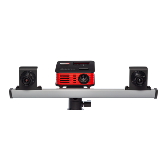
Page 10: Scanner Assembly
Scanner Assembly 1. Mount the cameras on the scanning module. 2. Install the scanning module on tripod. 3. Connect the projector with HDMI cable. 4. Connect cameras with USB cables. 5. Connect power supply and turn on the projector. *old color variant with identical specifications is pictured... -
Page 11: Scanner Setup
Scanner setup ScanCenter NG launch RangeVision ScanCenter If the scanner is not connected or drivers aren't installed, an indication will appear on the Start Screen, as shown below: Check the connection of cables, power supply, and then click Update. If you are sure that... -
Page 12: Select Scanning Zone
Selecting scanning zone After preparatory actions on setting up the computer, you should carry the scanner setting procedure. Select Configure scanner for a new area Calibration window on the Start screen and follow the instructions for each step. Before beginning the configuration, select the desired scan area (zone), depending on the object scanned. -
Page 13: Calibration Field Parameters
Calibration field parameters Take the necessary calibration to configure the scanner to the selected scan area. Make sure that the scan area is included in the package of your scanner. The exact size and measurement temperature are written on the label on the reverse side of the calibration plate. Enter these values into the Configuration Wizard or select from the drop-down list of previously entered values. Placing the calibration plate To find a working distance place the calibration plate in front one of the cameras. -
Page 14: Initial Setup Of Cameras And Lenses
Initial setup of cameras and lenses When you first set up the scanner, image from the cameras may not be in focus or can be too bright or too dark due to different external lighting conditions. Adjust camera lenses, so that the brightness is acceptable: without the red overexposed areas and not too dark. Lens adjustment is carried out by rotating the ring on the objective. Loosen (do not unscrew!) the retention screw and rotate the ring. Lens adjustment is carried out by the following elements: 1. The iris tuning ring 2. The iris ring retention screw 3. The focus tuning ring 4. The focus ring retention screw Do not completely remove the retaining screws of the lens rings, it is enough just to loosen them. After you finished tuning the lens, lock the adjustment rings with the screws provided. -
Page 15: Checking Camera Arrangement
Checking camera arrangement Images from right and left cameras can be mismatched or flipped. Use the buttons present on this step to arrange them correctly. If this setup wizard step is not needed after completion, it can be turned off by checking Don't show this step anymore box. It can be brought back by checking the Show the camera arrangement step in setup wizard box located in Settings → Software → Cameras menu. Finding a working distance The scanner has own working distance (distance to the object) for each scanning area. When you configure your scanner, this distance is determined by calibration plate. -
Page 16: Adjustment Of The Projector Focus
Adjustment of the projector focus During the scanner operation the projector project structured light to the object - coded lines and stripes. To ensure that the lines are sharp, the projector must be focused on the working distance of the scanner. By switching the mode "Lines and Stripes", adjust the focus of the projector, so that the lines on the calibration plate were as sharp as possible. Check and if it’s necessary to adjust the projector focus. -
Page 17: Bringing The Cameras Together
Bringing the cameras together For the work of the scanner it is necessary to point both cameras to the same position on the specified working distance. Install the calibration plate in front of the scanner on the found working distance (if you changed its position after the projector focusing procedure). Turn on the Cross light mode and aim the scanner to the calibration plate. It is not necessary to combine cross with marks on the plate at this stage, the focused projector should be projecting a cross on any surface, located at the working distance from the scanner. -
Page 18: Final Calibration Of The Cameras
Final calibration of the cameras After the cameras are positioned align the projected cross with the central mark on the calibration plate and proceed. Before setting the exposure adjust the sharpness of the lenses: 1. Turn on "Black light" projector mode. 2. Set the minimal exposure value (1) using the slider. 3. Open the lens iris as much as possible without getting overexposure. 4. Adjust the lens sharpness. It is convenient to use camera view zoom by left-clicking the camera views to assess sharpness. - Page 19 Set the projector to the lines and stripes mode. Set the exposure for the cameras between 30 and 60 (less if the scanning object is dark and more if it is bright). By default the value is 49~50. Areas illuminated with red mean overexposed areas where the image is too bright. Configure lenses iris so that the lines on the calibration plate are as bright as possible, but without a significant amount of excessive light. Image brightness of both cameras must be the same!
- Page 20 If you are setting up for the ”S” FOV, it may be necessary to decrease the brightness of lines and stripes due to the close distance to object. Decrease the brightness value, as shown in the figure. Brightness value of lines is approximately 2 times greater than the brightness of the stripes.
-
Page 21: Calibrating The Scanner
Calibrating the scanner You need to perform calibration in order to ensure the work of the scanner after the adjustment of lenses. Scanning software analyses the image of the plate, obtained from the cameras and compares it with the mathematical model, marked by the algorithm. There are 3 types of calibration: Full calibration, fast calibration (orientation) and Calibration of turntable (finding the table axis). Full calibration is used if: ● the lenses of the cameras need to be reconfigured (for example, if you change the scanning area), ● if you suspect that scanning accuracy got worse, ● after transporting the scanning complex. Orientation is used: if you suspect that the camera moved due to unreliable mounting, ● ● if you want to check the accuracy of performed calibration, ● before the work with the scanner (recommended). Calibration of rotary table is performed: in case of any change in the position of the rotary table to the scanner (when ● scanning on the rotary table). Calibration of rotary table is described in the Scanning on rotary table section. - Page 22 Calibration plate Calibration plate is a special plate with markers, the distance between which is measured with high accuracy. It is used for setting up a scanner and its calibration. For each scanning zone a separate calibration plate is used. There are three standard plates for Spectrum : L is the largest and S is the smallest. The approximate size of plates is specified in the Scanner setup section. For calibration of rotary table on the S scan area you should use the "axis evaluation" plate. In the picture below you can see different calibration plate examples.
-
Page 23: Full Calibration
Full calibration Full calibration dialog box opens automatically after the Configuration wizard or manually from the menu Configuration → Full calibration. Calibration procedure: 1. In the dropdown list the previously selected (in Сonfiguration wizard) calibration plate size is chosen. Compare it to the actual calibration field, choose it from the list, if needed. Focal distance of the lenses is detected automatically, and is only allowed to change by technical support specialist when calibration problems occur. 2. In accordance with the text prompt and symbol image install the calibration plate in the desired position. The brightness of the images of calibration plate can be adjusted with exposure controller. You should not allow very dark images or images with excessive brightness areas. Press the Capture button. Original plate position - the position at the working distance from the scanner (marking on the view from cameras matches the markers on the plate), the cross is projected on the central marker. - Page 24 In case if not all marks are found on the image, you will also see the error message. It may mean the following: ● not all markers are visible on one of the snapshots, not all markers are lit by the projector, ●...
- Page 25 Some advice on calibration: do not change the distance from the center of the plate to the scanner when ● turning the plate. The exception are only snapshots in positions 10 and 11, ● do not rotate the plate at a very high angle. Ensure that all marks on the plate are visible from both cameras, when you turn the table, ● be careful with calibration plates! It is not permitted to contaminate or perform any mechanical damage to the surface with the marks. After the use store the plates in designated case, before the calibration procedure ensure that cameras and cables are secure in ● the designated position.
-
Page 26: Fast Calibration (Orientation)
Fast calibration (orientation) The orientation can be started from the Calibration window on the Start screen. ● place the calibration plate at the working distance to the scanner (the first calibration position), press the Capture button, ● ● next, following the steps, make two more shots, ● after this the accuracy of orientation will be shown. It should be approximately equal to the accuracy value of the last calibration. -
Page 27: Focus Assessment During Calibration
Focus assessment during calibration While performing the calibration steps it is important to not deviate too much from the working distance in order to keep the calibration field in focus. The focus assessment option can help with this task. It is located in the Hardware settings →... - Page 28 Waste Electrical and Electronic Equipment Directive 2002/96/EC (WEEE). The mark indicates the requirement NOT to dispose the equipment as unsorted municipal waste, but use the return and collection systems according to local law. RangeVision, 2021...
Need help?
Do you have a question about the SPECTRUM and is the answer not in the manual?
Questions and answers