Table of Contents
Advertisement
Quick Links
Advertisement
Table of Contents

Subscribe to Our Youtube Channel
Related Manuals for Rangevision SMART ScanCenter 2016.2


Summary of Contents for Rangevision SMART ScanCenter 2016.2
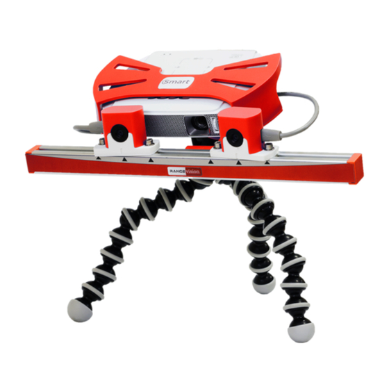
- Page 1 RANGEVISION SMART ScanCenter 2016.2...
- Page 3 Introduction Thank you for choosing RаngeVisiоn product. Please read the instructions for setting up and scanning before using the RаngeVisiоn Smart 3D scanner, as well as familiarize with the manual in processing the scan data in RangeVisiоn SсаnMerge. Here are described procedures preparing the scanner, installing the...
-
Page 4: Technical Specifications
Technical specifications Scanning zone Scanning area (mm) 500x375x375 300x225x225 150x112x112 3D resolution (mm) 0,24 0,12 3D point accuracy (mm) Up to 0.1% of scanning area size Resolution of cameras 1,3 Mpix Diagonal of the matrix 1/2’’ Scanning time ~12 sec Model calculation time ~8 sec 160х55х150 mm... -
Page 5: Package Contents
Preparing to work Package contents Scanning module with LED projector 2 USB cameras Cables (USB+HDMI) USB disk with the software License key Desktop flexible tripod Projector power supply Hex key (to adjust the position of the cameras) Calibration plate for scan zones №1,2 10. - Page 6 Installing software and drivers Connect USB disk with RangeVision logo to your PC and launch RangeVision ScanCenter setup Following the tips, choose the language, type and the path of installation. After copying the files install drivers and graphic libraries, which are necessary for correct functioning of RangeVision 3D scanner.
-
Page 7: Scanner Connection
Scanner connection Scanner assembly Remove the scanner from the case, install the scanner unit on the flexible tripod. If necessary, you can use any other tripod for photo and video equipment with a max load of 1 kg and mount 1/4 ''. The cameras are connected via MiniUSB connector, the projector is connected via HDMI. - Page 8 Cameras connection Connect cameras to USB ports of your computer. Make sure that USB ports work correctly. It's forbidden to use USB hub and connect cameras to one port! The scanner can't send data correctly with only one USB!
- Page 9 Silicon Labs, Arduino Uno, Rangevision Table and so on. For checking efficiency of the table, turn it for a little angle. On the menu choose Adjustment Table calibration. Enter the angle number and press Turn. The table must rotate clockwise, viewed from above.
-
Page 10: Scanner Setup
RаngeVisiоn SсаnCenter launch Turn on the projector and connect the scanner to the computer. In IDS Camera Manager check the connection and cameras availability. Run Rangevision ScanCenter. In order for program to work properly you need to run it as Administrator. - Page 11 Check the connection of cables, power supply, and then click Retry. If you are sure that all the components of the scanner are connected correctly and the connection error persists, click Skip to select your scanner settings manually. If necessary, contact the technical support of your reseller.
- Page 12 Configuration Wizard To configure Smart before scanning, launch Configuration wizard. It step by step describes all actions, necessary to configure the scanner. In addition, please carefully read this chapter. Scanning zones Before beginning the configuration, select the desired scan area (zone), depending on the object scanned.
- Page 13 Calibration field size Take the necessary calibration to configure the scanner to the selected scan area. Make sure that the scan area is included in the packaging of your scanner. The exact size is written on the label on the reverse of the calibration plate. Enter this value in the Configuration Wizard or select from the drop-down list of previously...
- Page 14 Initial setup of cameras Disconnect USB cable from the cameras, and using a hex key loosen the screws of cameras. Move the cameras, aligning the marks on their housing with the marks on housing of the scanner. On the smallest scan zone №3 the cameras are as close as possible, on scan zone №2 they correspond to the medium position, and scan zone №...
- Page 15 Working distance and projector focus Take the calibration plate in accordance with the selected scanning zone: large for scanning zones № 1,2, small for scanning zone № 3. Install the plate on the magnetic stand in front of the scanner. Scanning zone, №...
- Page 16 Calibration You need to perform calibration in order to ensure the work of the scanner after the adjustment of lenses. Specifically for this purpose we use the calibration plate, which pre-measured with high accuracy. Scanning software analyses the image of the plate, obtained from the cameras and compares it with the mathematical model, marked by the algorithm.
- Page 17 Be careful when selecting the plate, specifying its size, and during calibration! When the calibration is incorrect, there may be problems when scanning and you will receive model with distorted size. Specify the added plate in the list Select plate. When making a selection, settings of Lenses will automatically be changed.
- Page 18 Final precision is 0.** shows the calibration accuracy. Memorize the measured value and close the calibration menu. Short Calibration function (orientation) is used to test the accuracy of calibration. This is a simplified version of full calibration, the calculation occurs after the one capture of calibration plate in the initial position (at the working distance from the scanner).
- Page 19 Some advice on calibration: Do not change the distance from the center of the plate to the scanner when turning the plate. The exception are only snapshots in positions 10 and 11. Do not rotate the plate at a very high angle. Ensure that all marks on the plate are visible from both cameras, when you turn the table.
- Page 20 In RangeVision 3D scanner there are 3 scan options available, which are different, in the first place, by the fragment alignment method:...
-
Page 21: Creating A New Project
Creating a new project To start scanning create a new project in accordance with the selected scan method. Specify the location where you want to save the project and scan data. When you choose the path where you want to save the project, consider a large volume of scan data. - Page 22 Adjusting the exposure and brightness After you place an object at the needed distance, switch the projector to the Lines and Stripes lighting mode. Adjusting exposure of the cameras (the slider in the toolbar), get maximum exposure value, which does not cause red dots to appear on the lines. Areas of the image, not relating to the scanned object, don't matter.
- Page 23 Action Tool Rotation of the model Left mouse button Rotation of the model in the plane of the screen Left mouse button on the edges of the view Zooming/Deleting Middle mouse button (press mouse wheel Dragging the model in the plane of the screen Right mouse button You can simplify preview for decreasing time of redraw model.
- Page 24 Scanning without markers When scanning without markers, the fragments of the model surface may not be oriented in relation to each other, which decreases the scanning speed and the process of gaining a 3D-model. This scanning method may be used if the surface of the object has expressed assymetrical relief, which will later serve as basis for fragments registering.
- Page 25 Scanning with markers This scanning method is more convenient than scanning without markers. In addition to construction of the object surface, in this mode the scanner finds marks and calculates their coordinates. If each of the following scans has enough related marks from previous ones, new fragment automatically will be placed in the desired position.
- Page 26 If a project can not cover all necessary areas to scan without moving the object relative to the surface with markers, you need to create multiple projects (by number of positions of the object relative to the markers) and then during the processing load them together to combine.
- Page 27 Set the object at a working distance from the scanner Turn on Stripes and lines mode, check the sharpness of the projector and with the help of the slider adjust the exposure of cameras Start scanning with the corresponding button Scan the object in the next position, visually observing the correctness of fragments stitching in the 3D model viewing area.
- Page 28 When scanning with markers besides the above mentioned parameters in Settings you may also specify marker properties. When using customized markers, specified their radius in the corresponding field. Scanning with a turntable Scanning at turn table is executed without markers. The object of scanning is placed at the table platform and is scanned from several angles.
- Page 29 Scanning with texture 3D scanner RangeVision Smart has a feature of colored scanning. Obtaining a 3D model with texture can be achieved both through scanning with or without markers. Choice of scan mode is performed when you create a project:...
- Page 30 Before the scan, placing an object in front of the scanner at the working distance, adjust the illumination brightness, amplification and exposure. Set such values of the parameters at which the colors on the image from the cameras will be the most accurately matching the actual object colors.
- Page 31 Go in ScanMerge. The project, which is opened in ScanCenter, will be transferred to ScanMerge. RangeVision ScanCenter will continue to work in the background to maintain the operating temperature of the cameras. The projector can be turned off at this time.
Need help?
Do you have a question about the SMART ScanCenter 2016.2 and is the answer not in the manual?
Questions and answers