Table of Contents
Advertisement
Quick Links
Advertisement
Table of Contents

Related Manuals for Rangevision SPECTRUM


Summary of Contents for Rangevision SPECTRUM
- Page 1 RANGEVISION Setup a nd c alibration SPECTRUM ...
-
Page 2: Table Of Contents
Contents Introduction 3 Technical s pecifications 4 System r equirements 4 Preparing f or w ork Package c ontents 5 Installing s oftware a nd d rivers 7 Setting u p y our c omputer f or w ork w ith t he s canner ... -
Page 3: Introduction
Introduction Thank y ou f or c hoosing R аngeVisiоn pectrum! Please r ead t his m anual b efore u sing... -
Page 4: Technical S Pecifications
Scanning zone L M S Scanning Area (WxHxD) (mm) 520*400*400 320*250*220 120*90*100 3D point accuracy 0.12 mm 0.06 mm 0.04 mm Model Spectrum Resolution of cameras 3 Mpix Diagonal of the matrix 1/2” Texture scanning Yes 3D resolution Scanning zone L M S 3D resolution 0.25 mm 0.15 mm 0.06 mm ... -
Page 5: Preparing F Or W Ork
Preparing for work Package contents RаngeVisiоn 3D scanner is supplied in a protected road hard case. Camera tripod is placed in a separate bag. The scanner is equipped with three scanning areas. Scanning area is a calibration plate and stand for the calibration plate. 5 ... - Page 6 № Name qty. 1 Scanning m odule: Installation c onstruction w ith p rojector 1 1 Cable k it f or c onnection...
-
Page 7: Installing S Oftware A Nd D Rivers
RаngeVisiоn S саnCenter s etup . Following the prompts, select the desired language, type and path for installation. After the files have been copied install drivers and graphics libraries, necessary for the correct operation of RangeVision 3D scanner. If y ou... -
Page 8: Setting Up Your Computer For Work With The Scanner
Setting up your computer for work with the scanner For the correct operation of Rаngevisiоn 3D scanner you will need to setup your computer. This procedure is performed once before the first use of the scanner . Connecting projector Turn on the projector and connect it to the HDMI-port of your video card. After connecting the projector, it should be displayed in the system. If the computer has several video outputs, define the one to be used. Right c lick o n t he d esktop, s elect S creen r esolution , 2. -
Page 9: Configuring C Omputer P Arameters
Configuring computer parameters To avoid a recurrence of the problems during the scanner operation, you must turn off the screensaver and sleep mode. By clicking right mouse button on the desktop, select Personalize → Screensaver and turn off the screensaver, disable turning off the display and putting the computer in sleep mode. 9 ... -
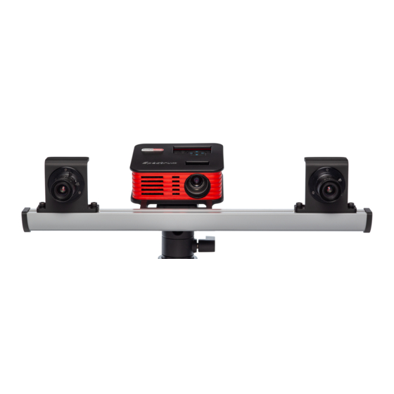
Page 10: Scanner A Ssembly
Scanner Assembly 1. Mount the cameras on the scanning module. 2. Install the scanning module on tripod. 3. Connect the projector with HDMI cable. 4. Connect cameras with USB cables. 5. Connect power supply and turn on the projector. *old c olor v ariant w ith i dentical s pecifications i s p ictured ... -
Page 11: Scanner S Etup
Scanner setup ScanCenter NG launch Run R angeVision S canCenter N G If t he s canner i s n ot c onnected o r d rivers... -
Page 12: Select S Canning Z One
Select scanning zone After p reparatory a ctions o n s etting u p t he c omputer, y ou s hould c arry he ... -
Page 13: Calibration F Ield P Arameters
Calibration field parameters Take the necessary calibration to configure the scanner to the selected scan area. Make sure that the scan area is included in the package of your scanner. The e xact s ize a nd m easurement t emperature a re w ritten o n t he l abel o n... -
Page 14: O F C Ameras A Nd L Enses
Initial setup of cameras and lenses When you first set up the scanner, image from the cameras may not be in focus or can be too bright or too dark due to different external lighting conditions. Adjust camera lenses, so that the brightness is acceptable: without the red overexposed areas and not too dark. Lens adjustment is carried out by rotating the ring on the objective. Loosen (do not unscrew!) the retention screw and rotate the ring. Lens adjustment is carried out by the following elements: 1. The iris tuning ring 2. The iris ring retention screw 3. The focus tuning ring 4. The focus ring retention screw Do not completely remove the retaining screws of the lens rings, it is enough just to loosen them. After you finished tuning the lens, lock the adjustment rings with the screws provided. 14 ... -
Page 15: Checking C Amera A Rrangement
Checking camera arrangement Images f rom r ight a nd l eft c ameras c an b e m ismatched o r f lipped. U se t he buttons present o n t his s tep t o a rrange t hem c orrectly. ... -
Page 16: O F T He P Rojector F Ocus
Adjustment of the projector focus During the scanner operation the projector project structured light to the object - coded lines and stripes. To ensure that the lines are sharp, the projector must be focused on the working distance of the scanner. By switching the mode "Lines and Stripes", adjust the focus of the projector, so that the lines on the calibration plate were as sharp as possible. Check and if it’s necessary to adjust the projector focus. Bringing the cameras together For the work of the scanner it is necessary to point both cameras to the same position on the specified working distance. Install the calibration plate in front of the scanner on the found working distance (if you changed its position after the projector focusing procedure). ... -
Page 17: Final C Alibration
Final calibration of the cameras After the cameras are positioned align the projected cross with the central mark on the calibration plate and proceed. 17 ... - Page 18 Before setting the exposure adjust the sharpness of the lenses: 1. Turn on "Black light" projector mode. 2. Set the minimal exposure value (1) using the slider. 3. Open the lens iris as much as possible without getting overexposure. 4. Adjust the lens sharpness. It is convenient to use camera view zoom by left-clicking the camera views to assess sharpness. Set the projector to the lines and stripes mode. Set the exposure for the cameras between 30 and 60 (less if the object, which you are planning to scan is dark and more if it is bright). By default the value is 45. 18 ...
- Page 19 Areas illuminated with red mean overlit areas with too bright image. Configure lenses iris so that the lines on the calibration plate are as bright as possible, but without a significant amount of excessive light. Image brightness of both cameras must be the same! 19 ...
- Page 20 If y ou a re s etting u p t he 3 rd s canning a rea, i t m ay b e n ecessary t o...
-
Page 21: Calibrating T He S Canner
Calibrating the scanner You n eed t o p erform c alibration i n o rder t o e nsure t he w ork... - Page 22 For e ach s canning z one a s eparate c alibration p late i s u sed. T here ...
-
Page 23: Full C Alibration
Full calibration Full c alibration d ialog b ox o pens a utomatically a fter t he C onfiguration w izard ... - Page 24 2. In accordance with the text prompt and symbol image install the calibration plate in the desired position. The brightness of the images of calibration plate can be adjusted with exposure controller. You should not allow very dark images or images with excessive brightness areas. Press the Capture button. Original plate position - the position at the working distance from the scanner (marking on the view from cameras matches the markers on the plate), the cross is projected on the central marker. ...
-
Page 25: Fast C Alibration ( Orientation)
After a ll t he n ecessary s napshots a re t aken, c alibration m odule w ill s tart a utomatically. ... - Page 26 The o rientation c an b e s tarted f rom he Calibration w indow on the S tart s creen ...
-
Page 27: Focus Assessment During Calibration
Focus assessment during calibration While performing the calibration steps it is important to not deviate too much from the working distance in order to keep the calibration field in focus. The focus assessment option can help with this task. It is located in the H ardware ... - Page 28 RangeVision, 2 020 28 ...
Need help?
Do you have a question about the SPECTRUM and is the answer not in the manual?
Questions and answers