Table of Contents
Advertisement
Quick Links
Advertisement
Table of Contents

Related Manuals for ADC Soneplex Wideband System 3190


Summary of Contents for ADC Soneplex Wideband System 3190
- Page 1 © 3190 ONEPLEX IDEBAND YSTEM NSTALLATION AND ERIFICATION UIDE HMS-357 List 4 Part Number: 150-2205-04 (Split Power) CLEI Code: T3M12H0E HMS-357 List 5 Part Number: 150-2205-05 (Redundant Power) CLEI Code: T3M13H0E ™800-357-104-01;¨ Section 800-357-104-01...
- Page 2 Contents herein are current as of the date of publication. ADC reserves the right to change the contents without prior notice. In no event shall ADC be liable for any damages resulting from loss of data, loss of use, or loss of profits, and ADC further disclaims any and all liability for indirect, incidental, special, consequential or other similar damages.
- Page 3 800-357-104-01, Revision 01 Using This Technical Practice SING ECHNICAL RACTICE The following conventions are used in this practice: • Monospace type indicates screen text. • Keys you press are indicated by small icons such as ENTER . Key combinations to be pressed simultaneously are indicated with a plus sign as follows: CTRL •...
- Page 4 Related Documentation 800-357-104-01, Revision 01 ELATED OCUMENTATION Document Number Title 400-100-100-xx TL1 Command Set Reference 150-357-200-xx HXU-357 List 1 Multiplexer Unit 150-358-100-xx HXU-358 List 1 Multiplexer Unit 150-359-100-xx HXU-359 List 1 Multiplexer Unit 150-357-100-xx HFA-357 List 1 Fan Assembly Unit 100-319-200-xx HTC-319 List 1 Test Card 350-319-200-xx...
- Page 5 800-357-104-01, Revision 01 Avis et Avertissements de Sécurité VIS ET VERTISSEMENTS DE ÉCURITÉ Les alimentations CC du boîtier doivent être branchées soit (1) à des sources 48 Vcc TBTS ou (2) à des sources qui sont isolées électriquement du secteur ca et qui sont reliées à la terre de façon fiable.
- Page 6 Avis et Avertissements de Sécurité 800-357-104-01, Revision 01 September 29, 2000 HMS-357 List 4 and List 5...
-
Page 7: Table Of Contents
800-357-104-01, Revision 01 Table of Contents ABLE OF ONTENTS Introduction _________________________________________________________________________ 1 Document Scope ..........................1 System Overview ..........................2 Before You Begin _____________________________________________________________________ 3 Reviewing Installation Plans......................3 Establishing a Method of Procedure ....................3 Unpacking and Inspecting the System Components................4 Mounting the Chassis __________________________________________________________________ 6 Installing the LIU, Module B—For the HXU-357 Multiplexer............8 Cabling the Chassis ___________________________________________________________________ 9 Drain Wire and Cable Tie Installation ....................9... - Page 8 Table of Contents 800-357-104-01, Revision 01 Placing the DS3 Transport In Service through the HXU-357 .......... 37 Installing the HXU-358 Multiplexer Card ..................38 Setting Up Basic System Parameters Through the Config Menu ........39 Entering the Card ID (System Name) through the Config Menu ........40 Configuring DS1 Services through the Config Menu............
- Page 9 800-357-104-01, Revision 01 Table of Contents Appendix A - System Specifications _____________________________________________________ 77 Interface Specifications........................77 Environmental Specifications ......................80 Physical Specifications ........................80 Power Specifications........................80 Power Requirements ........................81 A/B Power Sources ..........................82 Fuses..............................82 Appendix B - Technical Reference ______________________________________________________ 86 Compatibility ...........................86 System Products ..........................86 Compliance Standards........................87 Appendix C - Product Support _________________________________________________________ 88...
- Page 10 IGURES 1. System Overview ............................. 2 2. Mounting the Soneplex Wideband System 3190 in a CO Rack ..............6 3. Installing the 10BASE-T LIU, Module B......................8 4. Installing the Drain Wire and Cable Tie for All Amphenol Connectors ............9 5.
- Page 11 800-357-104-01, Revision 01 List of Figures 37. System Loopbacks and Test Access.......................67 38. Installing a Test Card into the HMS-357 .......................69 39. Installing a Cut-through Card into the HMS-357...................70 40. Power Access Connector (Specification) .......................77 41. Common Access Panel (Specification) ......................77 42.
- Page 12 List of Tables 800-357-104-01, Revision 01 IST OF ABLES 1. System Components ............................4 2. System Installation Notes ..........................5 3. Cable Connector Pinout and Color Code (16/16 Cable)................11 4. Cable Connector Pinout and Color Code (25/7 Cable).................. 11 5.
-
Page 13: Introduction
800-357-104-01, Revision 01 Introduction NTRODUCTION OCUMENT COPE This guide provides basic step-by-step instructions for installing several different shelf configurations and establishing a working system. Once you have completed the basic installation and verified that your system is functioning properly, you can refer to the technical practices for the individual components. The technical practices provide comprehensive configuration and technical information that will help you further define system parameters to meet your particular system requirements. -
Page 14: System Overview
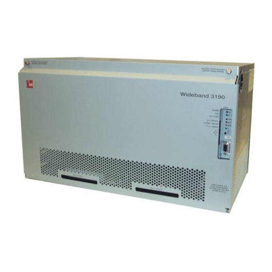
DACS Figure 1. System Overview The Soneplex Wideband System 3190 (HMS-357 List 4 and List 5) is an open-standards system that provides complete T1 and E1 deployment. Depending on your choice of multiplexer, the HMS-357 can transport T1 or E1 interfaces to filed locations from T1, E1, DS3, STS-1, or OC-3 network connectors. -
Page 15: Before You Begin
800-357-104-01, Revision 01 Before You Begin EFORE EGIN Prior to installing the Soneplex WBS-3190, it is important to prepare for the installation by • Reviewing installation plans through establishing a Method of Procedure • Unpacking and inspecting the system components, and •... -
Page 16: Unpacking And Inspecting The System Components
Before You Begin 800-357-104-01, Revision 01 NPACKING AND NSPECTING THE YSTEM OMPONENTS Following is then list of components available for the Wideband System 3190. Unpack your order and inspect for any damage that may have occurred during shipping. After inspecting each unit, sign for each item received. A notes sheet (see Table 2) has been provided to document any components not listed below. - Page 17 800-357-104-01, Revision 01 Before You Begin Table 1. System Components (Continued) ? ? ? ? Check ü ü ü ü Item Part Number Installer Initial Line Interface Unit Module B 150-2233-01 (required if you are installing an 10BASE-T HXU-357) Cables HCA-532 List 1 cable stub (50 ft.) 150-2218-01 HCA-532 List 2 cable stub (200 ft.)
-
Page 18: Mounting The Chassis
12-24 x ½ Screws Figure 2. Mounting the Soneplex Wideband System 3190 in a CO Rack Verify that the battery feed is disconnected. For single shelf installation only: to fulfill NEBS requirements, a 4-inch gap above and below the unit is necessary. - Page 19 800-357-104-01, Revision 01 Mounting the Chassis Installer Check ü ü ü ü Step Procedure Install a mounting bracket on each side of the Wideband System 3190 chassis using the four (6-32 x ) screws provided for each bracket. Mounting brackets and screws are contained in the installation kit.
-
Page 20: Installing The Liu, Module B-For The Hxu-357 Multiplexer
Mounting the Chassis 800-357-104-01, Revision 01 LIU, M B—F HXU-357 M NSTALLING THE ODULE OR THE ULTIPLEXER The Line Interface Unit (LIU) Module A is preinstalled with the Wideband System 3190. Module A is used for HXU-358 (DS3) and HXU-359 (STS-1) multiplexers, as well as for subtending STS-1 systems from an OC-3 multiplexer. -
Page 21: Cabling The Chassis
800-357-104-01, Revision 01 Cabling the Chassis ABLING THE HASSIS The Wideband System 3190 allows for several network interface configurations: • DS3 (see “Installing Interface Cables—DS3 or STS-1 Only” on page • STS-1 (see “Installing Interface Cables—DS3 or STS-1 Only” on page •... -
Page 22: Cable Connector Pinouts
Cabling the Chassis 800-357-104-01, Revision 01 Step Procedure Attach the drain wire of the female amphenol cable connector to the screw hole of the male amphenol backplane connector and tighten the drain wire to the backplane with one 4-40 x screw. -
Page 23: Cable Connector Pinout And Color Code (16/16 Cable)
800-357-104-01, Revision 01 Cabling the Chassis Table 3. Cable Connector Pinout and Color Code Table 4. Cable Connector Pinout and Color Code (16/16 Cable) (25/7 Cable) Ring Pins Tip Pins Ring Pins Tip Pins Connector Connector Pin Connector Connector Pin Color Code Slot Slot... -
Page 24: Selecting The Proper Installation Procedures
Cabling the Chassis 800-357-104-01, Revision 01 ELECTING THE ROPER NSTALLATION ROCEDURES This practice divides the cable installation procedures of each shelf configuration into tabbed sections (see Figure 6). Select the tabbed section that applies to your configuration and only follow those procedures. Installing Interface Cables HELF ONFIGURATION... -
Page 25: Installing Interface Cables-Ds3 Or Sts-1 Only
800-357-104-01, Revision 01 —DS3 STS-1 O NSTALLING NTERFACE ABLES DSX-1 (In) DSX-1 (Out) 10Base2 OSS RS-232 PORT AUX RS-232 PORT 10BaseT HMU DSX-1 CONFIGURATION DS3 CONFIGURATION DSX-1/DS3 CONFIGURATION 3192 MECH DSX (XMT FROM MUX) TIP DSX (XMT FROM MUX) RING TO CO MDF TO CO MDF DSX (RCV TO MUX) TIP... -
Page 26: Installing Interface Cables-Dsx-1 Only
800-357-104-01, Revision 01 —DSX-1 O NSTALLING NTERFACE ABLES To CO MDF To CO MDF DSX-1 (In) DSX-1 (Out) 10Base2 OSS RS-232 PORT AUX RS-232 PORT 10BaseT HMU DSX-1 CONFIGURATION DS3 CONFIGURATION DSX-1/DS3 CONFIGURATION 3192 MECH DSX (XMT FROM MUX) TIP DSX (XMT FROM MUX) RING TO CO MDF TO CO MDF... -
Page 27: Installing Interface Cables-Dsx-1 And/Or Ds3/Sts-1 Only
800-357-104-01, Revision 01 —DSX-1 DS3/STS-1 O NSTALLING NTERFACE ABLES To CO MDF To CO MDF DSX-1 (In) DSX-1 (Out) 10Base2 OSS RS-232 PORT AUX RS-232 PORT 10BaseT HMU DSX-1 CONFIGURATION DS3 CONFIGURATION DSX-1/DS3 CONFIGURATION 3192 MECH DSX (XMT FROM MUX) RING DSX (XMT FROM MUX) TIP TO CO MDF TO CO MDF... -
Page 28: Installing Interface Cables-Oc-3 (Dual Subtended Sts-1 Multiplexers)
800-357-104-01, Revision 01 —OC-3 (D STS-1 NSTALLING NTERFACE ABLES UBTENDED ULTIPLEXERS This procedure requires the installation of an HXU-369 multiplexer to complete. See “Installing the HXU-369 Multiplexer Card” on page 52 prior to starting this cable installation. Prior to installing the interface cable, you must install a DS3 Module in the Module B location (see “Installing the DS3 LIU, Module B”... -
Page 29: Installing Cables For Dual Subtended Sts-1 Multiplexers From An Oc-3 Network (Backplane View)
800-357-104-01, Revision 01 After installing the LIU, proceed the cable installation. DSX-1 (Out) DSX-1 (In) 10Base2 OSS RS-232 PORT OSS RS-232 PORT AUX RS-232 PORT 10BaseT HMU 10BaseT HMU DSX-1 CONFIGURATION DS3 CONFIGURATION DSX-1/DS3 CONFIGURATION 3192 MECH DSX (XMT FROM MUX) TIP DSX (XMT FROM MUX) RING TO CO MDF TO CO MDF... - Page 30 800-357-104-01, Revision 01 After installing the cables, proceed the OC-3 fiber-optic cabling instructions. Transceiver r G a P a i C la ro du G a in To fiber P a ir network HXU-369 Fiber cable Figure 12. Routing OC-3 Fiber-Optic Cables Through the Lower Access Hole (Left-Hand Side, Front View) Installer Check ü...
-
Page 31: Wiring The Common Access Panel
800-357-104-01, Revision 01 Wiring the Common Access Panel IRING THE OMMON CCESS ANEL DSX-1 TEST ACCESS AUX 2 CRT AUD ACTIVE CRT VIS MAJ AUD MAJ VIS (DEFAULT) MIN AUD BITS TIMING RING MIN VIS SYS ID Figure 13. Common Access Cover Plate Installer Check ü... -
Page 32: Installing The Power Cables
Installing the Power Cables 800-357-104-01, Revision 01 NSTALLING THE OWER ABLES Terminal block Ferite ESD strap input Figure 14. Opening the Ferite and Routing the Battery Feed Wires (Right-Hand Side, Rear View) -48 VA Return and -48 VB Return are tied together on the backplane and are referenced as RTN on the connector. - Page 33 800-357-104-01, Revision 01 Installing the Power Cables 8-32 x ¼ screws ESD strap input Ground lug Figure 15. Grounding the Chassis (Right-Hand Side, Rear View) Installer Check ü ü ü ü Step Procedure (continued) All connections to terminal block TB1 must be done to local codes. Connect a 12 AWG gauge wire to the -48 V RTN terminal in position 3 of the Power Access connector.
-
Page 34: Connecting The Network Interface
Connecting the Network Interface 800-357-104-01, Revision 01 ONNECTING THE ETWORK NTERFACE 10Base2 OSS RS-232 PORT OSS RS-232 PORT AUX RS-232 PORT 10BaseT HMU 10BaseT HMU Figure 16. Network Interface Connections For all network connections, shielded cables are required. For 10BASE-T connections, Category-5 shielded cables are required. Installer Check ü... -
Page 35: Pinouts For 10Base-T Interface
800-357-104-01, Revision 01 Connecting the Network Interface Table 6. Pinouts for 10BASE-T Interface Description NC = no connection. Table 7. Pinouts for DB-25 OSS Interface (DTE) Description Description NMA TX NMA TCLK NMA RX NMA RTS- NMA RCLK NMA CTS- NMA DSR- NMA RTN NMA DTR-... -
Page 36: Pinouts For Db-25 Aux Interface (Dte)
Connecting the Network Interface 800-357-104-01, Revision 01 Table 8. Pinouts for DB-25 AUX Interface (DTE) Description Description AUX TX AUX2 RX AUX2 RTS- AUX2 CTS- AUX2 DSR- AUX2 RTN AUX2 DTR- NC = no connection. September 29, 2000 HMS-357 List 4 and List 5... -
Page 37: Installing A Management Unit (Hmu)
800-357-104-01, Revision 01 Installing a Management Unit (HMU) (HMU) NSTALLING A ANAGEMENT ESD strap input HMU-319 H iG U -3 a in N IT IT IC M IN Figure 17. Installing an HMU Installer Check ü ü ü ü Step Procedure Whenever installing or removing units from the HMS-357 chassis, be sure to wear an antistatic wrist strap and connect it to the ESD strap input. -
Page 38: Connecting A Local Maintenance Terminal
Installing a Management Unit (HMU) 800-357-104-01, Revision 01 ONNECTING A OCAL AINTENANCE ERMINAL Maintenance terminal Serial COM port HMU Craft port Interface cable Figure 18. Connecting a Maintenance Terminal to the HMU Craft Port Installer Check ü ü ü ü Step Procedure The HMU DCE should be connected to the DTE port of the local maintenance terminal. -
Page 39: Using The Terminal Access Option
800-357-104-01, Revision 01 Installing a Management Unit (HMU) SING THE ERMINAL CCESS PTION You can use the Terminal Access Option (TAO) interface to access and manage all the components of the HMS-357, including the line units, multiplexers, shelf, and the associated doublers and remote units. Depending on the Transaction Language 1 (TL1) release version you are using, there are two logon procedures. - Page 40 Installing a Management Unit (HMU) 800-357-104-01, Revision 01 Installer Check ü ü ü ü Step Procedure From your terminal emulation program, locate the release version as shown in Figure • For TL1 release version 3.04, proceed to Step • For TL1 release version 3.05, proceed to Step At the prompt, enter tao and then press ENTER...
-
Page 41: Configuring The Management Unit
(page • Setting the Ethernet connection for HXU-357 multiplexers only (page If you forget your password, contact ADC customer service (see “Appendix C - Product Support” on page 88). For more information about passwords, refer to the HMU technical practice. -
Page 42: Setting The Hmu Date And Time (Option H)
Installing a Management Unit (HMU) 800-357-104-01, Revision 01 Setting the HMU Date and Time (Option H) Setting the HMU date and time will globally configure these parameters for all HLU-319s in the system. The HMU-319 List 7A will also globally update the time and date settings for the HXUs in the chassis. -
Page 43: Setting The Local Ip Address (Option A)
800-357-104-01, Revision 01 Installing a Management Unit (HMU) Setting the Local IP Address (Option A) Installer Check ü ü ü ü Step Procedure ENTER From the Shelf Options menu, press and then press to select Local IP Address for the HMU. At the prompt, enter the local IP address using the XXX.XXX.XXX.YYY format, where XXX and YYY are decimal numbers from 0 through 255. -
Page 44: Installing Multiplexers
Installing Multiplexers 800-357-104-01, Revision 01 NSTALLING ULTIPLEXERS The HMS-357 can be configured with the following multiplexer cards: • HXU-357—DS3 (see “Installing the HXU-357 Multiplexer Card” on page • HXU-358—DS3 (T1/E1) (see “Installing the HXU-358 Multiplexer Card” on page • HXU-359—STS-1 (see “Installing the HXU-359 Multiplexer Card”... -
Page 45: Installing The Hxu-357 Multiplexer Card
800-357-104-01, Revision 01 Installing Multiplexers HXU-357 M NSTALLING THE ULTIPLEXER ESD strap input Card eject tab MUX card Figure 21. Installing an HXU-357 Installer Check ü ü ü ü Step Procedure Whenever installing or removing units from the HMS-357 chassis, be sure to wear an antistatic wrist strap and connect it to the ESD strap input. -
Page 46: Setting Up The Communications Channel Through The Hxu-357
Enter the assigned IP address for the HXU-357. For more information on IP addressing, refer to “Network Specifications” on page When using an HXU-357, a 10BASE-T module (ADC part number 150-2233-01) is necessary for network management. Press to exit the screen, then press to confirm and save the setting and return to the root menu of the Shelf Status screen. -
Page 47: Setting Up Basic Hxu-357 System Parameters In The System Administration Menu
800-357-104-01, Revision 01 Installing Multiplexers Setting Up Basic HXU-357 System Parameters in the System Administration Menu Installer Check ü ü ü ü Step Procedure From the Shelf Status screen, press to log onto the HXU-357. For more information on navigating through the menu system, refer to the procedures detailed in “Setting Up the Communications Channel through the HXU-357”... -
Page 48: Configuring Ds1 Services Through The Hxu-357
Installing Multiplexers 800-357-104-01, Revision 01 Configuring DS1 Services through the HXU-357 This section provides instructions for configuring a single line from the HXU Root Menu. After the DS1 line is configured, the line unit, any necessary doublers, and the HRU are installed as described in the sections which follow. -
Page 49: Configuring The Ds3 Transport Through The Hxu-357
800-357-104-01, Revision 01 Installing Multiplexers Configuring the DS3 Transport through the HXU-357 The DS3 transport is configured in accordance with network requirements. Installer Check ü ü ü ü Step Procedure From the Configuration Management submenu, press and then press ENTER to select Configure DS3 Interface. -
Page 50: Installing The Hxu-358 Multiplexer Card
Installing Multiplexers 800-357-104-01, Revision 01 HXU-358 M NSTALLING THE ULTIPLEXER ESD strap input Card eject tab MUX card Figure 22. Installing an HXU-358 Installer Check ü ü ü ü Step Procedure Whenever installing or removing units from the HMS-357 chassis, be sure to wear an antistatic wrist strap and connect it to the ESD strap input. -
Page 51: Setting Up Basic System Parameters Through The Config Menu
800-357-104-01, Revision 01 Installing Multiplexers Setting Up Basic System Parameters Through the Config Menu Main Monitor History Config Test Inventory Quit Help +-------------------+ | T1/E1 Ports | DS3 Port | Password Date and Time | +--------------------------------+ | | Date (mm/dd/yy) : 01/18/00 | | Time (hh:mm:ss) : 14:12:30 | +--------------------------------+... -
Page 52: Entering The Card Id (System Name) Through The Config Menu
Installing Multiplexers 800-357-104-01, Revision 01 Entering the Card ID (System Name) through the Config Menu M a i n M o n i t o r H i s t o r y C o n f i g T e s t I n v e n t o r y Q u i t H e l p... -
Page 53: Configuring Ds1 Services Through The Config Menu
800-357-104-01, Revision 01 Installing Multiplexers Configuring DS1 Services through the Config Menu Main Monitor History Config Test Inventory Quit Help +-------------------+ T1/E1 Ports +--------------------------------------------------------------------+ |Port Srvc Mode Code T1/E1 | Port Srvc Mode Code T1/E1| MEM-ADMIN HDB3 OUT-OF-SRVC 133 B8ZS OUT-OF-SRVC HDB3 OUT-OF-SRVC 133... - Page 54 Installing Multiplexers 800-357-104-01, Revision 01 Installer Check ü ü ü ü Step Procedure (Continued) Proceed to “Configuring the DS3 Transport through the Config Menu” on page ? ? ? ? Installer Signature Date September 29, 2000 HMS-357 List 4 and List 5...
-
Page 55: Configuring The Ds3 Transport Through The Config Menu
800-357-104-01, Revision 01 Installing Multiplexers Configuring the DS3 Transport through the Config Menu Main Monitor History Config Test Inventory Quit Help +-------------------+ | T1/E1 Ports DS3 Port +-----------------------------------------------------------+ | Service Mode(OUT OF SERVICE,IN SERVICE..): IN SERVICE | Protection Mode (PROTECTED,UNPROTECTED) : UNPROTECTED | DS3 Mode (M13,C-BIT) : C-BIT... -
Page 56: Installing The Hxu-359 Multiplexer Card
Installing Multiplexers 800-357-104-01, Revision 01 HXU-359 M NSTALLING THE ULTIPLEXER ESD strap input Card eject tab MUX card Figure 27. Installing an HXU-359 Installer Check ü ü ü ü Step Procedure Whenever installing or removing units from the HMS-357 chassis, be sure to wear an antistatic wrist strap and connect it to the ESD strap input. -
Page 57: Setting Up Basic System Parameters Through The Config Menu
| In case of Date/Time change all PM statistics will be discarded | (TAB) next field (ENTER) activate (ESC) quit +-----------------------------------------------------------------+ ID: ADC | Card 'B' 5/19/00 05:41:16 ALARMS: WARN Figure 28. Setting the Date and Time Through the HXU-359 Installer Check ü... -
Page 58: Entering The Card Id (System Name) Through The Config Menu
| +--------------------------+ | | | ID: | +--------------------------+ | (ENTER) activate (ESC) quit | +------------------------------+ ID: ADC | Card 'B' 05/19/00 05:41:31 ALARMS: WARN Figure 29. Setting the Card ID Through the HXU-359 Installer Check ü ü ü ü Step... -
Page 59: Setting The System Clock Synchronization Through The Config Menu
| Force : Normal +--------------------------------------------+ | (TAB) next field (Spacebar) next value (ENTER) activate (ESC) quit | +--------------------------------------------------------------------+ ID: ADC | Card 'B' 05/19/00 05:40:36 ALARMS: WARN Figure 30. Setting the Clock Configuration Through the HXU-359 Installer Check ü ü ü ü... - Page 60 Installing Multiplexers 800-357-104-01, Revision 01 Installer Check ü ü ü ü Step Procedure (Continued) To manually force the clock synchronization mode, set Force to the desired mode. Configure the following options: • Normal (default) • Primary • Secondary • Internal •...
-
Page 61: Configuring Ds1 Services Through The Config Menu
NONE +----------------------------------------------+ | (TAB) next field (Spacebar) next value (ENTER) activate (ESC) select srv. | +---------------------------------------------------------------------------+ ID: ADC | Card 'B' 05/19/00 05:36:35 ALARMS: WARN Figure 31. Setting Up DS1 Services Through the HXU-359 Installer Check ü ü ü ü... - Page 62 Installing Multiplexers 800-357-104-01, Revision 01 Installer Check ü ü ü ü Step Procedure (Continued) Proceed to “Configuring the STS-1 Transport through the Config Menu” on page ? ? ? ? Installer Signature Date Do not configure a service as OOS-M or OOS-A when it is selected as a clock synchronization source.
-
Page 63: Configuring The Sts-1 Transport Through The Config Menu
NONE +----------------------------------------------------------+ | (TAB) next field (Spacebar) next value (ENTER) activate (ESC) quit | +--------------------------------------------------------------------+ ID: ADC | Card 'B' 05/19/00 05:40:16 ALARMS: WARN Figure 32. Setting Up the STS-1 Transport Through the HXU-359 Installer Check ü ü ü ü... -
Page 64: Installing The Hxu-369 Multiplexer Card
Installing Multiplexers 800-357-104-01, Revision 01 HXU-369 M NSTALLING THE ULTIPLEXER ESD strap input Card eject tab MUX card Figure 33. Installing an HXU-369 If you have already installed the HXU-369 multiplexer at this point as outlined in “Installing Interface Cables—OC-3 (Dual Subtended STS-1 Multiplexers)” on page 16, proceed to “Installing a Fan Assembly (Optional)”... - Page 65 800-357-104-01, Revision 01 Installing Multiplexers Installer Check ü ü ü ü Step Procedure (Continued) Repeat Step 3 through 6 for the other HXU-369. To set the internal clock as the synchronization source Set clk int and then enter at the TL1 command line prompt.
-
Page 66: Installing A Fan Assembly (Optional)
Installing Multiplexers 800-357-104-01, Revision 01 NSTALLING A SSEMBLY PTIONAL ESD strap input Fan assembly Thumb screw Molex fan cable Thumb screw Figure 34. Installing the Fan Assembly (Cover Down) The HFA-357 fan assembly is installed from the front of the chassis, above the multiplexer tray. The fans begin operating as soon as the cable is connected. -
Page 67: Placing The Fan Under Hmu Management
800-357-104-01, Revision 01 Once the fan assembly is installed, it must be placed under HMU management. Placing the Fan Under HMU Management Installer Check ü ü ü ü Step Procedure The following procedure assumes proper TAO login. For proper login procedure, please refer to “Using the Terminal Access Option”... -
Page 68: Installing A Line Unit (Hlu)
800-357-104-01, Revision 01 (HLU) NSTALLING A strap input HLU-319 Figure 35. Installing a Line Unit into the Wideband Chassis Installer Check ü ü ü ü Step Procedure Whenever installing or removing units from the HMS-357 chassis, be sure to wear an antistatic wrist strap and connect it to the ESD strap input. -
Page 69: Installing A Remote Unit (Hru)
800-357-104-01, Revision 01 (HRU) NSTALLING A EMOTE Standard 400/200 Interface DS1TIP DS1RING HDSL2RING1 HDSL2TIP1 _ ( ) 48V Local Power _ ( ) Circuit Ground DS1 RING1 HDSL1 RING Remote enclosure HDSL1TIP DS1TIP1 Chassis Ground* * Chassis Ground may be tied to Earth Ground per local practice. Note: Active pins are highlighted in black. -
Page 70: Setting Up Circuit Ids
800-357-104-01, Revision 01 Installer Check ü ü ü ü Step Procedure (Continued) Proceed to “Setting Up Circuit IDs” on page ? ? ? ? Installer Signature Date The craft port on an HRU can be accessed for configuration whether or not it is managed by an HMU. Refer to “Configuring the Management Unit”... -
Page 71: Placing The Line In Service
800-357-104-01, Revision 01 LACING THE INE IN ERVICE After the line installation is complete, the line must be placed in service by: • enabling the alarms on the HLU • placing the DS1 interface in service at the HXU Placing the HLU Under HMU Management Installer Check ü... -
Page 72: Placing The Line Unit In Service At The Hxu
800-357-104-01, Revision 01 Placing the Line Unit in Service at the HXU The Wideband System 3190 interfaces internally to the 28 lines at the common DSX-1 point. Once a line has been configured on the HLU, the DS1 interface at the HXU should be placed In-Service. Some alarm reporting will be lost if the line is not placed In-Service. - Page 73 800-357-104-01, Revision 01 Enabling Alarms for Systems Using an HXU-357 Multiplexer Installer Check ü ü ü ü Step Procedure From the Shelf Options screen, press to select Alarm Management. The following prompt appears: Which Line Unit do you want to change the alarm settings on (1-28).
- Page 74 800-357-104-01, Revision 01 Placing the Line Unit in Service Using an HXU-358 Multiplexer Installer Check ü ü ü ü Step Procedure The following procedure assumes proper TAO login. For proper login procedure, please refer to “Using the Terminal Access Option” on page From the Shelf Options screen, select Select the Config menu and then press...
- Page 75 800-357-104-01, Revision 01 Enabling Alarms for Systems Using an HXU-358 Multiplexer Installer Check ü ü ü ü Step Procedure From the Shelf Options screen, press to select Alarm Management. The following prompt appears: Which Line Unit do you want to change the alarm settings on (1-28).
- Page 76 800-357-104-01, Revision 01 Placing the Line Unit in Service Using an HXU-359 Multiplexer Installer Check ü ü ü ü Step Procedure The following procedure assumes proper TAO login. For proper login procedure, please refer to “Using the Terminal Access Option” on page From the Shelf Options screen, select Select the Config menu and then press...
- Page 77 800-357-104-01, Revision 01 Enabling Alarms for Systems Using an HXU-359 Multiplexer Installer Check ü ü ü ü Step Procedure From the Shelf Options screen, press to select Alarm Management. The following prompt appears: Which Line Unit do you want to change the alarm settings on (1-28).
- Page 78 800-357-104-01, Revision 01 Placing the Line Unit in Service Using an HXU-369 Multiplexer Installer Check ü ü ü ü Step Procedure The following procedure assumes proper TAO login. For proper login procedure, please refer to “Using the Terminal Access Option” on page From the Shelf Options screen, select Select the Config menu and then press...
-
Page 79: Troubleshooting And System Testing
800-357-104-01, Revision 01 Troubleshooting and System Testing ROUBLESHOOTING AND YSTEM ESTING Figure 37 shows system loopbacks and test access points. You can do additional system tests through test cards (see “Installing a Test Card (HTC) (Optional)” on page 69). You can route multiplexer output to provide local access to any DS1 or E1 channel on the DS3 transport at an electrical DSX-1 or E1 cross-connect point using cut-through Cards (see “Managing Alarms”... -
Page 80: System Loopback Definitions
Troubleshooting and System Testing 800-357-104-01, Revision 01 Table 9. System Loopback Definitions Test Point Loopback Definition Terminal loopback to the customer at the DS3 line. Activate from the HXU-358 Test menu. (a) (b) TLB3 Facility loopback to the network at the DS3 line. Activate from the HXU-358 Test menu. (a) (b) FLB3 (a) (b) -
Page 81: Installing A Test Card (Htc) (Optional)
800-357-104-01, Revision 01 Troubleshooting and System Testing (HTC) (O NSTALLING A PTIONAL The HTC-319 Test Card provides you with an easy method of testing Central Office (CO) and Field Tip and Ring transmit and receive pairs. strap input HTC-319 Figure 38. Installing a Test Card into the HMS-357 Installer Check ü... -
Page 82: Installing A Cut-Through Card (Hcc) (Optional)
Troubleshooting and System Testing 800-357-104-01, Revision 01 (HCC) (O NSTALLING A THROUGH PTIONAL The HCC-319 Cut-through card allows you to route the output of multiplexers to HDSL lines. ESD strap input HCC-319 Figure 39. Installing a Cut-through Card into the HMS-357 Installer Check ü... -
Page 83: Line Unit Testing
800-357-104-01, Revision 01 Troubleshooting and System Testing ESTING Once the line unit is installed, verify that it is operating properly. To do this, monitor the following: • Status LED • Messages reported by the front-panel display. Verification without a Downstream Device If there is no downstream device installed: Step Procedure... -
Page 84: Managing Alarms
ANAGING LARMS The Soneplex Wideband System 3190 system reports alarms from the shelf, the line units, the fan assembly and the multiplexer unit. The HMS-357 displays an alarm summary on the HMU at all times. Any alarm that exists in the system is represented by a critical, major or minor alarm LED on the HMU front panel. -
Page 85: Hxu Alarms
800-357-104-01, Revision 01 Managing Alarms To silence the alarm, do one of the following: • Press the ACO pushbutton on the front panel of the HMU. • Press the external ACO pushbutton (if installed). The following events occur: • The front panel ACO LED lights and remains lit until the original alarm is cleared or until another alarm occurs. - Page 86 Managing Alarms 800-357-104-01, Revision 01 The line unit H1ES, H2ES, and DS1 Errored Seconds Threshold alarms are not supported by the Shelf Status menu. If any of these conditions exist on a line unit, the line unit status indicates NORMAL. For this reason, use of the line unit Errored Seconds Threshold alarm option is not recommended.
-
Page 87: Network Specifications
TL1 or require download functions must use 10BASE-T. 10BASE-T also makes troubleshooting larger systems much easier. ADC recommends placing the WBS-3190 on its own LAN. Any connection to a larger network should be done through a router with the appropriate firewall protection. Selecting the IP address, subnet mask, TCP/IP server address and trap addresses are basically arbitrary, but some understanding of these functions is still required to make an informed choice. -
Page 88: Routers Or Gateways
Network Specifications 800-357-104-01, Revision 01 a device to determine which IP addresses are located on the local network and which addresses must go to the gateway for forwarding. An IP address of 200.200.200.1 and a subnet mask of 255.255.255.0, for example, indicate that only IP addresses, which start with 200.200.200, can be found on the local physical network, and that all other addresses must go through the gateway. -
Page 89: Appendix A - System Specifications
800-357-104-01, Revision 01 Appendix A - System Specifications A - S PPENDIX YSTEM PECIFICATIONS NTERFACE PECIFICATIONS Figure 40 shows the wirewraps for the power access connector, which are accessible from the backplane when covers are removed. Figure 40. Power Access Connector (Specification) DSX-1 TEST ACCESS AUX 2... - Page 90 Appendix A - System Specifications 800-357-104-01, Revision 01 Table 14. RJ-45 Pinout for 10BASE-T Interface to HMU (J34) Description +XMT output -XMT output +RCV input -RCV input Cable must be shielded category 5. Table 15. RS-232 DB-25 OSS Interface to HMU (DTE) - Male Connector Description output input...
- Page 91 800-357-104-01, Revision 01 Appendix A - System Specifications Table 16. RS-232 DB-25 HMU Craft Interface (DCE) - Female Connector Description output input input input output Cable must be shielded. Table 17. RS-232 DB-25 AUX Interface to HMU (DTE) Description output input input input...
-
Page 92: Environmental Specifications
Appendix A - System Specifications 800-357-104-01, Revision 01 NVIRONMENTAL PECIFICATIONS The WBS-3190 is designed to meet NEBS CO requirements. Temperature (Min./Max.) Operational 32° to 122°F (0° to +50°C) Non-operating -40° to 140°F (-40° to +60°C) Operational Altitude 197 ft. (60m) below sea level to 13,000 ft. (3962m) above sea level Relative Humidity Operational... -
Page 93: Power Requirements
800-357-104-01, Revision 01 Appendix A - System Specifications OWER EQUIREMENTS Each system must be individually fused to support redundant power feeds. The HMS-357 List 4 provides a split-power backplane to limit the current requirements of each battery feed line to less than 20A for any configuration. -
Page 94: A/B Power Sources
To avoid complex calculations, use the following simplified power and fan requirements. • If PairGain/ADC components are used and no CPE power is required, the Wideband System 3190 chassis can power up to 12 doublers without necessitating the use of fans. (Recommended components include the HLU-319 List 5, the HDU-409, the HRU-402, and the HRU-411.) -
Page 95: Power Consumption And Power Dissipation For Multisystem Configurations
800-357-104-01, Revision 01 Appendix A - System Specifications Table 18. Common Equipment Power Consumption Power Consumption Equipment Current Draw (mA) (Watts) Power Dissipation (Watts) HXU-357 List 1 (2 units) 353 typ. 612 max. 15 typ. 26 max. 15 typ. 26 max. HMU-319 List 7 118 typ. -
Page 96: Hdsl Transport Line Configurations
Appendix A - System Specifications 800-357-104-01, Revision 01 Table 20. HDSL Transport Line Configurations Power Power Number of Consumption Dissipation Line Doubler Doublers per Current Draw per Line per Line Type Line Units Units Line Remote Units per Line (mA) (Watts) (Watts) HLU-319... - Page 97 800-357-104-01, Revision 01 Appendix A - System Specifications For a 0°C to 50°C (32°F to 122°F) operating environment, a fan assembly is required for any of these situations: One system with ≥ 230W power dissipation • Four systems with ≥ 948W power dissipation •...
-
Page 98: Appendix B - Technical Reference
However, due to FCC and NEBS testing guidelines, compliance is not guaranteed with all vendors when tested as a system. ADC has verified that all its standard line units are in compliance with these guidelines when tested as a system in our HMS-357 shelf. It is the customer’s responsibility to verify that other vendor’s equipment meets system-level compliance when installed in our chassis. -
Page 99: Compliance Standards
800-357-104-01, Revision 01 Appendix B - Technical Reference OMPLIANCE TANDARDS Table 23. Compliance Standards Standard Description GR-499-CORE Transport System Generic Requirements (TSGR): Common Requirements Issue 1, December 1995 GR-63-CORE New Equipment-Building System (NEBS) Generic Equipment Requirements Issue 1, October 1995 GR-1089-CORE Electromagnetic Compatibility and electrical Safety Generic Criteria for Network Issue 1, July 1994... -
Page 100: Appendixc - Product Support
ADC Customer Service Group provides expert pre-sales and post-sales support and training for all its products. ECHNICAL UPPORT Technical support is available 24 hours a day, 7 days a week by contacting the ADC Wireline Systems Division Customer Service Engineering Group at one of the following numbers: Telephone: 800.638.0031 or 714.730.3222... - Page 101 Pack the equipment in a shipping carton. Write the ADC Wireline Systems Division address and the Return Material Authorization Number you received from Customer Service clearly on the outside of the carton and return to: ADC Wireline Systems Division 14352 Franklin Ave.
-
Page 102: Appendix D - Abbreviations
Appendix D - Abbreviations 800-357-104-01, Revision 01 D - A PPENDIX BBREVIATIONS HRU: HiGain Remote Unit HTC: HiGain Test Card ACO: Alarm Cutoff HXU: HiGain Multiplexer Unit AIS: Alarm Indication Signal ALM: Alarm AMI: Alternate Mark Inversion Internet Protocol ASCII: American Standard Code for Information Interchange In-Service B8ZS: Binary 8 Zero Substitution LED:... - Page 103 800-357-104-01, Revision 01 Appendix D - Abbreviations SSC2: Special Signaling Channel 2 STS-1: Synchronous Transport Signal Level -1 TAO: Terminal Access Option TL1: Transaction Language 1 TLB: Terminal Loopback TLOS: Transmit Loss of Signal VTG: Virtual Tributary Group VTS: Virtual Tributary Slot HMS-357 List 4 and List 5 September 29, 2000...
- Page 104 800-357-104-01, Revision 01 ROJECT EMBER IGNATURES Complete the following table by printing the title and name of each project member followed by their respective signatures. This list may then be removed and stored for future reference. Table 24. Signatures ? ? ? ? Title Name Signature...
- Page 105 800-357-104-01, Revision 01 NSTALLATION ERIFICATION BY ECTION Reviewed Installation Plans H H H H Check ü ü ü ü if not applicable (see “Reviewing Installation Plans” on page ? ? ? ? Shift Supervisor Signature Date Established Method of Procedure H H H H Check ü...
- Page 106 800-357-104-01, Revision 01 Cabled Chassis H H H H Check ü ü ü ü if not applicable (see “Cabling the Chassis” on page ? ? ? ? Shift Supervisor Signature Date Wired Common Access Panel H H H H Check ü ü ü ü if not applicable (see “Wiring the Common Access Panel”...
- Page 107 800-357-104-01, Revision 01 Installed Line Card(s) H H H H Check ü ü ü ü if not applicable (see “Placing the Line Unit in Service at the HXU” on page ? ? ? ? Shift Supervisor Signature Date Installed Remote Unit(s) H H H H Check ü...
-
Page 108: Index
Index 800-357-104-01, Revision 01 NDEX Numerics Ethernet connection ...............31 10BASE-T module Module B ............... 8 placing under HMU management ........55 Addresses ................75 Fan assembly Addresses, hardware and IP ..........75 installation ..............54 Air flow ................... 3 Fan block ................19 Alarms FCC compliance ..............99 HMU ................ - Page 109 800-357-104-01, Revision 01 Index configuring the DS3 transport ........37 mounting the chassis ............6 DS1 services ..............36 OC-3 ................16 enabling alarms ............61 placing line in service at HXU ........60 placing the DS3 transport in service ......37 placing line in service at HXU-357 ......60 HXU-358 placing line in service at HXU-358 ......62 configuring DS1 services ..........
- Page 110 Index 800-357-104-01, Revision 01 shelf Identifier .............. 30 Space requirements ..............3 Method of procedure ............... 3 Specifications ................77 Multiplexer environmental ...............80 HXU-357 ..............33 interface ................77 HXU-358 ..............38 physical .................80 HXU-359 ..............44 Standards compliance ............99 clock synchronization source ......19 STS-1 multiplexers ..............16 HXU-369 ...............
-
Page 111: Certification And Warranty
ADC during the 90-day warranty period is, at ADC’s option, either (a) return of the price paid or (b) repair or replace of the software. ADC also warrants that, for a period of thirty (30) days from the date of purchase, the media on which software is stored will be free from material defects under normal use. - Page 112 ADC DSL Systems, Inc. 14402 Franklin Avenue Tustin, CA 92780-7013 Tel: 714.832.9922 Fax: 714.832.9924 Technical Assistance 800.638.0031 714.730.3222...
Need help?
Do you have a question about the Soneplex Wideband System 3190 and is the answer not in the manual?
Questions and answers