
Related Manuals for JETWAY FFI02 Series


Summary of Contents for JETWAY FFI02 Series
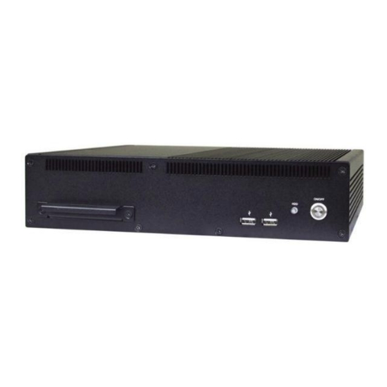
- Page 1 Quick Installation Guide NO. G03-FFI02QIG-F Rev: 1.0 Release date: 2021-12-13 Notice: The photos in this file are for illustration purpose only. The model may not be the latest version. Please refer to the product you purchased for actual specification.
-
Page 2: To Open The Chassis
I. To Open the Chassis Locate the screws in the spots marked on Turn over the bare bone system with the the top cover of the system and unscrew heatsink upwards, as the photo shows. them one by one. Remove the screws in the marked spots on Remove the screws in the marked spots on the front panel. - Page 3 Remove the IO panels and lift the cover up For CPU installation, user needs to remove to open the chassis. For user to have a the screws on the marked spots to clear view of layout, we may unplug some of dissemble the motherboard form chassis the cables during installation.
- Page 4 II. To Install CPU Find CPU socket on the board. Please make Remove the plastic protective cover from the sure that CPU socket is facing towards you socket (Put it to the original place if CPU is and the level is on you right hand side. not installed.
- Page 5 Alignment Key Alignment Key Golden Finger Indicator Make sure that Pin-1 Golden Finger Indicator in the place as shown in the above photo and match the two alignment keys on the CPU with two points of the socket. CPU can only be correctly installed in this direction. Incorrect installation might cause damage to CPU.
- Page 6 III.To Install Heatsink Thermal pads Bottom Side Paste Here! P/N: Tear off the HCS310HS1-F* 2pcs Protective films 60*52*1.0mm Find the above CPU heatsink and CPU thermal pad package. Remove the protective films on the both sides of the pad and apply it upon the bottom side of the heatsink for better heat conduction.
- Page 7 4. Turn the board over and lock the heatsink to the board by tightening the screws (P/N: LCSC378M01-F*4) on the marked spots. 5. Thermal pads need to be attached to the bottom of the motherboard, which will help the system to dissipate heat (P/N: HCSHBFFHS1-1F*9).
- Page 8 *Note: There should be one more HCS310HS1-F / HCS3XXHS2-F / HCSHBFFHS1-1F left as spare parts after normal assembly. User can use them to replace corresponding damaged thermal conductive pads. Notice : Please restore the screws that lock the motherboard to the chassis cover when CPU & heatsink installation completed.
- Page 9 2. Insert the gold-figure side of the compatible SO-DIMM into the slot at a 30 degree angle. See to it that the break of the module fit into the notch of the slot. 3. Press down to secure the SO-DIMM to the slot. The eject tabs will lock automatically if installing direction is correct.
- Page 10 V. To Install M.2 E-Key (2230) PCIe card Locate the M.2. PCIe, type-2230 slot on Remove the marked screw nut reserved the board. for M.2 PCIe card installation first. 3. Insert the gold-figure side of compatible card 4. Lock the card to the board by tightening up into M.2.
- Page 11 5. Locate the reserved Wi-Fi antenna holes on the back panel. Remove the dust-proof plugs on the marked spots from the panel to install the antenna, as the following details show. Back-side View: Put the metal ring into the antenna head at first, and then push this antenna head into antenna hole of the rear panel.
- Page 12 6. The metal hats on the end of the antenna 7. Tear off the tape to find metal hats of string are sealed by acetate tape to avoid Wi-Fi antenna string. possible damage to the system. 8. Press the metal hat on the end of the 9.
- Page 13 VI. To Install M.2 B-Key (3042/3052) card 1. Locate the M.2 B-Key, type-3042/3052 slot on 2. Remove the marked screw with a screwdriver. the board. 3. Insert the gold-figure side of compatible M.2 4. Install the screw back to the original spot. 3042 card into the slot until the golden finger side fully emerged into the slot.
- Page 14 VII. To Install M.2 M-Key (2280) card Locate the M.2 M-Key, type-2280 slot on the Remove the marked screw with a screwdriver. board. 3. Insert the gold-figure side of compatible M.2 4. Install the screw back to the original spot. 2280 card into the slot until the golden finger side fully emerged into the slot.
- Page 15 VIII. To Install Hard Disk 1. Remove the screws in the marked spots on the front panel. 2. Lock the SATA hard disk to one of the racks by tightening the screws in the marked spots.
- Page 16 3. Lock the SATA hard disk to the other rack by tightening the screws in the marked spots. 4. Insert the gold-figure side of the compatible STAT HDD into the slot.
- Page 17 5. Install the screw back to the original spot. 6. Find the compatible SATA cable for the system in the accessories package.
- Page 18 7. Plug this side of the cable to SATA power-in 8. Lock the racks with SATA HDD installed connector and SATA connector of the hard disk. to its original places by tightening the screws in the marked spots. 9. Plug the other sides of the cables into the SATA power connector and SATA port connector on the board.
- Page 19 Notice: When all necessary installations are finished, please make sure that all cables unplugged before installations are connected to their original places before restoring the back cover to the chassis and screws on the front panel/back panel/top cover locked to its original places (Refer to Part I). See to it that the cables inside are not blocked or pressed.
- Page 20 Wall mount the system by tightening two screws in the marked positions. Then tighten up the other two screws in the marked positions on the other rack.
Need help?
Do you have a question about the FFI02 Series and is the answer not in the manual?
Questions and answers