Advertisement
Quick Links
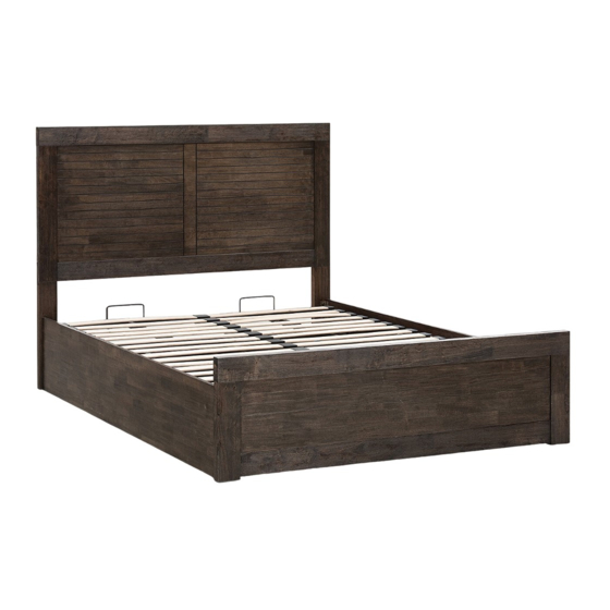
1399mm
Imported by Amart Furniture Pty Ltd,Qld, Brisbane Australia. For any assistance
with assembly or for missing parts please phone Amart Furniture, Customer
Service Freecall 1800 351 084.
Furniture
1622mm
2203mm
ASSEMBLY INSTRUCTION
VIKA GAS LIFT QUEEN BED
ITEM CODE - 64086
Imported by Amart Furniture Pty Ltd,Qld, Brisbane Australia.
For any assistance with assembly or for missing parts please phone
Amart Furniture, Customer Service Freecall 1800 351 084.
1
64086
Advertisement

Subscribe to Our Youtube Channel
Related Manuals for Amart Furniture 64086


Summary of Contents for Amart Furniture 64086
- Page 1 For any assistance with assembly or for missing parts please phone Amart Furniture, Customer Service Freecall 1800 351 084. 1622mm 1399mm 2203mm Imported by Amart Furniture Pty Ltd,Qld, Brisbane Australia. For any assistance with assembly or for missing parts please phone Amart Furniture, Customer Service Freecall 1800 351 084. 64086...
-
Page 2: Pre-Assembly Preparation
4. The packaging and contents can be a choking hazard, therefore keep out of reach of small children at all items. 5. Do not over tighten the bolts as this may damage the thread. ALLOW 45 MINUTES 2 PEOPLE REQUIRED TOOL REQUIRED 64086... -
Page 3: Parts List
ALLEN KEY - M6 PLASTIC CAP c/w HEX NUT,SPRING & FLAT PLASTIC CAP WASHER M x 6pcs N x 32pcs O x 16pcs P x 1pc M14 SPANAR M12.8 SPANAR Q x 1pc R x 1pc S x 1pc 64086... - Page 4 STEP 1: Assemble the bed post L/R '2' to the headboard panel '3' with minifix screws 'A' and wood dowel B' as shown . ALLEN KEY - M8 STEP 2: Fix headboard frame '1' and head post L/R with bolts 'D' and allen key 'Q' as shown. 64086...
- Page 5 STEP 3: Assemble the left & right side rails '5''6' to the center wood panel '7' with minifix screws 'A' and wood dowel 'B' as shown. STEP 4: Fix headboard and footboard '4' with bolts 'E' and allen key 'Q' as shown. 64086...
- Page 6 Then, fix bolts 'G' using allen key 'Q' first as shown in diagram 5.2 and do not tighten yet. Finally, fix all bolts and tighten as shown in diagram 5.3. 11/12 Hydraulic Pump right installation. 64086...
- Page 7 STEP 7: Assemble front & back frames bed base with flat washer M8 'I', base nut 'J' and bolts 'H' using allen key 'Q' and than fix base handles to the bed base with bolts 'L' using allen key 'P' as shown. STEP 8: Place base panels ' 8 ' & ' 9 ' as shown. 64086...
- Page 8 Each wood slat must be inserted with a single end and double end plastic cap as shown on the picture. STEP 10: Assemble the bed base on the right & left hydraulic frame and fix bolts starting from '1' to '3' as shown. Important note : Do not tighten the bolts yet! 64086...
- Page 9 STEP 11: Adjust the bed base, make sure distance with the front footboard approximately 15mm to above as shown. Important Note : Tighten all screws. 15mm to above ASSEMBLY COMPLETE 64086...
- Page 10 CAUTION : PLEASE USE HYDRAULIC PUMP STOPPER FOR SAFETY PURPOSE. 64086...
- Page 11 PLEASE PLACE THE MATTRESS ON THE BED. PLEASE NOTE THAT THE WEIGHT OF THE MATTRESS IS REQUIRED TO HELP CLOSE THE BED. TO LOWER THE SLEEPING PLATFORM STAND AT THE FOOT END OF THE BED AND PUSH SHARPLY DOWNWARDS USING BOTH HANDS. 64086...
- Page 12 Do not allow plastic to come in direct contact with your furniture. Chemicals in the • plastic of placemats etc. may soften and mark the finish if left in contact with the furniture for a period of time. 64086...
Need help?
Do you have a question about the 64086 and is the answer not in the manual?
Questions and answers