Table of Contents
Advertisement
Quick Links
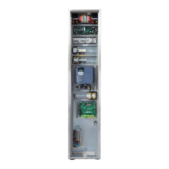
SETRONIK 1 Restyling
Cabinet at landing
(MRL)
Control panels, push-buttons panels and prewired systems for lifts
Via San Carlo 13 - 20010 Bareggio - Milano - ITALY
Tel: +39 02 90 36 34 99 - Fax: +39 02 90 36 35 00
Internet: www.seasystems.it - e-mail: sea@seasystems.it
U
SER MANUAL
Control panel
Cabinet in the shaft and
at landing (MRL)
SEA SYSTEMS S.r.l
Encoder on
car roof
Machine room
cabinet (MR)
STK1R-EN-95-0-A
rev0
06/04/2022
Advertisement
Table of Contents

Related Manuals for SEA SETRONIK 1 Restyling


Summary of Contents for SEA SETRONIK 1 Restyling
- Page 1 Control panels, push-buttons panels and prewired systems for lifts STK1R-EN-95-0-A Via San Carlo 13 - 20010 Bareggio - Milano - ITALY rev0 Tel: +39 02 90 36 34 99 - Fax: +39 02 90 36 35 00 06/04/2022 Internet: www.seasystems.it - e-mail: sea@seasystems.it...
-
Page 2: Table Of Contents
0.21 R ..........................34 ESERVED PARAMETER 0.22 | 0.23 | 0.24 U STK1R ...................35 PDATING BOARD SOFTWARE 0.25 | 0.26 | 0.27 | 0.28 | 0.29 | 0.30 R .................36 ESERVED PARAMETERS © 2022 Sea Systems Page 2 of 113... - Page 3 NCODER 8.11 | 8.12 | 8.13 R ........................... 77 ESERVED 8.14 S .................78 LOWDOWN DISTANCE FOR SECONDARY HIGH SPEED 8.15 R ............................... 78 ESERVED 8.16 SRS )....................78 MAGNET POSITION WITH NCODER © 2022 Sea Systems Page 3 of 113...
- Page 4 LARM CODES DISPLAYED AT PARAMETER SHAFT LEARNING WITH ENCODER 10. REMOTE CONTROL................113 11. TECHNICAL SUPPORT...............113 12. WARRANTY..................113 List of changes from “STK1R-EN-94-0-A rev0” to “STK1R-EN-95-0-A rev0” Page Description Release software New parameter 1.28 New alarm 31 © 2022 Sea Systems Page 4 of 113...
-
Page 5: Introduction And Field Of Application
Used to indicate an information whose content, if not observed, may cause minor injuries to persons or damages to the lift plant. ANGER Used to indicate that the described operation can cause physical injuries, if not performed in accordance with safety regulations. © 2022 Sea Systems Page 5 of 113... -
Page 6: Safety Precautions
If the lift is sold or transferred to a new owner, always make sure that all of the following documentation is transferred so that it can be consulted by the new owner and/or installer. Sea Systems provides the following documentation for each plant: manual for installation and use (this document) ... -
Page 7: Functional Characteristics
RELÈ Opto-insulated (compliant with EN81-20 EN81-50 EN81-1 EN81- AFETY CHAIN MONITORING INPUTS -10 ... +65 °C PERATING TEMPERATURE With microcontroller ONTROL LOGIC Permanent ATA STORAGE 12Vdc, 2…7Ah according to needs ECHARGEABLE BATTERIES © 2022 Sea Systems Page 7 of 113... -
Page 8: Installation And Tests
Follow the ‘safety precautions’ listed in chapter 2 during installation. Under no circumstances SEA SYSTEMS S.r.l. will be held liable for any damage arising from failure to comply with the instructions below, or for any unauthorized modification of the original equipment. -
Page 9: Fixing Of The Control Panel
5. Attach the flexible cables to the wedge bracket at such a point that when the car is at the lowest point, the flexible cable bag does not touch the bottom of the pit. © 2022 Sea Systems Page 9 of 113... -
Page 10: Attaching And Connecting The Car Position Sensors And The Relative Magnets
5.6. Attaching and connecting the car position sensors and the relative magnets SEA SYSTEMS S.r.l. provides various types of shaft sensors depending on the application. Each solution is outlined by one of the following installation diagrams. 1. Attach the shaft sensors and the relative magnets according to the indications on the relative diagram. - Page 11 These distances depend on the speed of the lift and the technical characteristics of the motor or the hydraulic unit installed. > minimum distance between adjacent floors, it is necessary to install the VEN01 encoder shaft system. © 2022 Sea Systems Page 11 of 113...
- Page 12 - hydraulic/electric relevelling - early door opening *) The orientation of these magnets depends on the sensor manufacturer / model. The figure shows the correct orientation with CARLO GAVAZZI model FMPB2 sensor. © 2022 Sea Systems Page 12 of 113...
- Page 13 These distances depend on the speed of the system and the technical characteristics of the motor or the hydraulic unit installed. > minimum distance between adjacent floors, it is necessary to install the VEN01 encoder shaft system. © 2022 Sea Systems Page 13 of 113...
- Page 14 These distances must be about 10 cm smaller than the slowdown distances set in parameters 8.05.0 8.06.0 SELF LEARNING OF FLOOR HEIGHTS AND STOP DISTANCES For automatic acquisition of floor heights and stop distances, see parameter 9.00. © 2022 Sea Systems Page 14 of 113...
- Page 15 To avoid excessive noise, it is absolutely necessary to attach the pulleys bracket of the encoder ECN01 on the arch of the car, and not on covering plates. ADJUSTING THE TENSION OF THE TOOTHED BELT Extend the spring until it has a length of 17 cm © 2022 Sea Systems Page 15 of 113...
-
Page 16: Connecting And Using Of The Stk2-Pm Programmer
3. Make sure that there are no active alarms (see parameter 0.01). In case of alarms refer to the chapter “9. Anomalies and Solutions”. 4. Cancel any old alarms that were recorded during installation / maintenance operations (see parameter 0.03.0) © 2022 Sea Systems Page 16 of 113... -
Page 17: Insulation Tests
8. disconnect the control panel from any other control panel belonging to an array of lifts 9. for any device not supplied by SEA SYSTEMS, always follow the manufacturer instructions. For example, if you use VEGA B- LIFT series 8120 evo light curtain along with the CPB12/24 control unit supplied by 0/24V coming from the STK1R control panel, you have to disconnect the supply conductors of CBP12/24 (DC IN terminals) before performing any test, because its electrical circuits are not insulated from the ground (G terminal) and from the metallic frame of the light curtains. -
Page 18: Test Procedure Of The Ucm Protection System, For Stk1R-A3 Control Panels
7. Move the car by making a call. Check that the lift is put out of service and that the alarm 81 is active (see parameter 0.01) 8. Reset the alarm (by using the SW1 push-button on the STK1R board or the parameter 0.03) 9. Reconnect the wire under the TC terminal (undo step 6) © 2022 Sea Systems Page 18 of 113... - Page 19 The test of the self monitoring function of the GMV NGV-A3 valve involves simulating the malfunction of the RUN and READY signals and checking for the activation of the alarm 81. To this end, see the manufacturer's user manual of the NGV-A3 valve. © 2022 Sea Systems Page 19 of 113...
- Page 20 Please follow the specific instructions provided by the manufacturer (MORIS Italia). See, for example, the "Use and maintenance manual" of the KMI device, page 13. In case of block following a UCM event identified by the KMI device, the STK1R control board signals the alarm 94. © 2022 Sea Systems Page 20 of 113...
-
Page 21: Test Of The Safety Circuit Cs4
4. Check that the bypasses are now open (led “10” and “X8” off) and that the “K2” led is off 1. Reconnect the wire under the terminal T12 (undo step 3). Check that the bypasses are still open and the led “K2” is off. © 2022 Sea Systems Page 21 of 113... -
Page 22: Test Of The Limit Switches
(for example alarms 97 and 420 must be disabled setting respectively timer 4.41 to zero and 4.34 to its maximum value). This also applies to alarms from other devices (VVVF inverter, soft starter, etc.) © 2022 Sea Systems Page 22 of 113... -
Page 23: Test Of The Can Bus
CAN2+ and CAN2- on multiplex systems): it must be 68 ohm ± 7 ohm. Larger values indicate that at least one termination is missing, smaller values that more than two terminations have been inserted. The correct position of the terminations can only be checked visually. © 2022 Sea Systems Page 23 of 113... -
Page 24: Programming
VO.xx : virtual output (i.e. output function) xx, assignable to a programmable physical output. See paragraph “6.xx Outputs ”. EEO : Electrically Emergency Operation UCM : Unintended Car Movement, according to EN81-20 standard SAPB : single automatic push-button operation © 2022 Sea Systems Page 24 of 113... -
Page 25: Lift State
(i.e. with the automatic switch FA open) may now be modified even in presence of that voltage (i.e. with the automatic switch FA closed) © 2022 Sea Systems Page 25 of 113... -
Page 26: Active Alarms Causing Out Of Service
Time elapsed from when the alarm was 0 0 2 activated, first part: days (00009999) DG56 = [0.02.3] Time elapsed from when the alarm was 0 0 2 0 0 activated, second part: hours (0023) © 2022 Sea Systems Page 26 of 113... -
Page 27: Alarm Reset / Alarm Log Erasing
It is never necessary, rather it is strongly advised not to erase the alarms log, • especially when there are anomalies and the customer wishes to contact SEA SYSTEMS for any clarification about them. By erasing the errors log, important informations are deleted that could be very useful to understand the causes of such anomalies. -
Page 28: Upward And Downward Run Counts
0 0 7 thousands (00009999) DG456 = [0.07.1] downward re-levelling count, second 0 0 7 0 part: units (000999) To reset all the re-levelling counters, set the cursor on DG3456 and press ˅ © 2022 Sea Systems Page 28 of 113... -
Page 29: Door State And Commands
VI.86=1 (maintenance operation), in absence of maintenance up / down commands (VI.58=0 and VI.59=0) • VI.12=1 and/or VI.22=1 (stop command for door 1 and 2, respectively) • VI.49=0 with parameter 1.23.0=1 (bypass of door safety contacts is active) © 2022 Sea Systems Page 29 of 113... -
Page 30: Car Movement Commands
Car is moving downward [0.09.2] ALLS DISABLING No new call is disabled (lift work normally) New external (floor) calls are disabled New internal (car) calls are disabled New external and internal calls are disabled © 2022 Sea Systems Page 30 of 113... -
Page 31: Setting The Maintainer Password
LOSS OF PARAMETER SETTINGS This parameter makes the modified parameters permanent. If this operation is not performed, the parameter settings will be lost if the power to the STK1R board is cut off. © 2022 Sea Systems Page 31 of 113... -
Page 32: Operating Time Of Stk1R Board
DG56 = VERSION 0 1 5 DG34 = REVISION DG56 = CUSTOM VERSION Any written reference to a software release must consist of these 4 numbers separated by dots: SERIES.VERSION.REVISION.CUSTOM_VERSION (1.46.0.0, for example). © 2022 Sea Systems Page 32 of 113... -
Page 33: Loading A Parameter Set
If the operation is successfully, the programmer turns off and on again, displaying 0.00.xxxx. After the command has been executed DG3456 will indicate: AAAA: Operation underway BBBB: Operation completed with success EEEE: Operation completed with errors © 2022 Sea Systems Page 33 of 113... -
Page 34: Stk1R Board Temperature
Unique serial number of the STK1R board DG34 = year of production (00FFh) 0 2 0 _ DG56 = month of production (00FFh) 0 2 0 DG3456 = sequential number (0000FFFFh) 0.21 Reserved parameter 0 2 1 © 2022 Sea Systems Page 34 of 113... -
Page 35: 0.24 Updating Stk1R Board Software
6, skipping point 6.1, because led HD4 is already lighted. 9. Remove the USB pen drive. 10. Enter the activation codes communicated by SEA SYSTEMS in parameters 0.22 and 0.23. 11. Enter 0001 at parameter 0.24 and check the result of the unlocking operation on DG3456, as shown in... -
Page 36: Eserved Parameters
The buzzer sounds when a car call push-button is pressed (EN81-70) and in case of car overload. Overload takes precedence. During out of service, all acoustic signals generated by the CAB01 buzzer are suppressed. 0.32 Reserved parameter © 2022 Sea Systems Page 36 of 113... -
Page 37: Sms Sending
V : voltage on input Contact toward +24V VTH : threshold voltage 5.xx.00.yy V < VTH open closed 5.xx.00.yy V > VTH closed open 5.xx.01.yy V > VTH closed open 5.xx.01.yy V < VTH open closed © 2022 Sea Systems Page 37 of 113... -
Page 38: Sw1 Push-Button Functions - All Led Signalling Mode
Setting the cursor on DG3 … DG6, a note will be output from the buzzer on the STK1R board with a frequency which depends on the state of the IS and ID sensors, as shown in the following table. Note © 2022 Sea Systems Page 38 of 113... -
Page 39: State Of Some Virtual Inputs Dealing With The Doors
• turning off and on again the STK1R controller board • resetting the STK1R controller board • Instead, the test is not stopped by turning off or disconnecting the STK2-PM programmer. © 2022 Sea Systems Page 39 of 113... -
Page 40: Programming The Driver, Operation, Shaft Sensors
Magnetic reed switches SIS and SID (for lifts) Synchronous encoder (encoder on the car roof, driven by a toothed belt) Magnetic reed switches SIS and SID (for elevating platforms) Asynchronous encoder (encoder on the motor shaft) Reserved © 2022 Sea Systems Page 40 of 113... -
Page 41: Programming The Number Of Stops
DESIGNATED FLOOR IN CASE OF FIRE IREFIGHTER ACCESS FLOOR Floor number, 01 is the lowest floor 0124 DG56 [1.03.1] (EN81-73) DESIGNATED FLOOR IN CASE OF FIRE Floor number, 01 is the lowest floor 0124 © 2022 Sea Systems Page 41 of 113... -
Page 42: Other Settings For En81-72 / En81-73 Operation
When the car lands at the designated floor, all doors enabled to open at that floor are opened, unless one or more of these are excluded from opening by parameters 1.24.0 and 1.24.1. © 2022 Sea Systems Page 42 of 113... -
Page 43: Car Door Type
Electronically controlled door motor / directly driven by contactors, removed O/C commands, forced closing command while car is running, with only the opening limit switch Serial controlled car door operator Fermator VF7-CAN “SEA“ (see note 5), permanent O/C commands Serial controlled car door operator Fermator VF7-CAN “SEA” (see note 5), removed O/C commands, with forced closing command while car is running 26 …... - Page 44 STK1R-EN-95-0-A INSTALLATION AND USE rev0 STK1R control panels (Setronik1 Restyling) 06/04/2022 SEA SYSTEMS Door operator Fermator VF7-CAN “SEA” is special version of the VF7-CAN operator customized with the following CAN identifiers: CAN identifiers Messages (see Fermator instructions Door 1 Door 2...
- Page 45 For all serial controlled car door operators (for example 24, 25, 31, 32), virtual inputs VI.46, VI.47, VI.48 (sensitive edge) and VI.23, VI.24, VI.51 (photocell/ light curtain) are processed in logical OR with the same signals generated and transmitted by the serial operator. © 2022 Sea Systems Page 45 of 113...
-
Page 46: R E - Levellings / Early Door Opening / Alarm 20
Reduced headroom controlled by 2 supplementary limit switches in series (see VI.18) and supplemental CS4 safety circuit (see VI.74). If the limit switches does not function in normal operation, alarm 095 is activated. © 2022 Sea Systems Page 46 of 113... - Page 47 204 … 209 : STK1R supply voltages out of bounds 260 : reserved 261 : reserved To enable normal operation, the value of the parameter 1.08.0 must be changed. © 2022 Sea Systems Page 47 of 113...
-
Page 48: In-Use Signalling, In-Car Presence Sensor, Gong, Retractable Cam
The condition VI.90=0 and VI.89=1 does not activate the busy signal The condition VI.90=0 and VI.89=1 activates the busy signal The condition VI.90=0 and VI.89=1 activates the busy signal and inhibits the activation of the retractable cam (virtual output VO.6) © 2022 Sea Systems Page 48 of 113... -
Page 49: Car Position Signals
0.25 <= V < 0.35 ● ● ● ● ○ ○ 0.35 <= V < 0.45 ● ● ● ● ● ○ 0.45 <= V < 0.55 ● ● ● ● ● ● 0.55 <= V © 2022 Sea Systems Page 49 of 113... -
Page 50: Automatic Emergency Operation / Enabling Of The Electrical Emergency Operation In Absence Of Mains
For automatic emergency operations, the shaft must have SIZ1 and SIZ2 sensors (for shafts without an encoder) or a SIZ1 sensor (for shafts with an encoder). © 2022 Sea Systems Page 50 of 113... -
Page 51: Control Panel Operating Temperature Limits
Landing call push-buttons are in common with all lifts in the group (i.e. any landing call is connected to all lift control panels) There are separated landing call push-buttons for each lift the group © 2022 Sea Systems Page 51 of 113... -
Page 52: Unintended Car Movement (Ucm) / Safety Gear Tripping Device
The lack of safety chain voltage does not cause incorrect signals from the shaft sensors With 1.16.0=0 any interruption (even short) of the safety chain voltage necessarily invalidates the car position information, forcing a re-phasing travel on the next call. © 2022 Sea Systems Page 52 of 113... -
Page 53: Landing / Car Can Bus Error Logging
1.17 Landing / car CAN bus error logging 1 1 7 0 0 0 [1.17.0] CAN1 bus error logging (landing / car CAN bus) Alarms from 270 to 273 are not logged Alarms from 270 to 273 are logged © 2022 Sea Systems Page 53 of 113... -
Page 54: Max Switching Frequency Of Contactors / Contactorless Vvvf
“Excessive closing time” alarms (see alarm 77, 79 and 86) With automatic car doors, the cam is retracted as soon as all the doors are closed (0.08=CCC0), also if there are “Excessive closing time” alarms (see alarm 77, 79 and 86) © 2022 Sea Systems Page 54 of 113... -
Page 55: Car-Lift Semaphores / Car-Lift Side Photocells
Departure is enabled if the safety chain and the car doors are closed (useful, for example, for lifts with the landing doors unlock operated by a fixed cam). Detection of alarms 43 and 44 is enabled. © 2022 Sea Systems Page 55 of 113... -
Page 56: Shabbat" Operation
2 seconds from the first pressure. If the operation is successfully completed, the booking signals of the landing calls of the lowest floor will flash 5 times (also when the reset is done by means of VI.50). © 2022 Sea Systems Page 56 of 113... -
Page 57: Operation - Functions Of Virtual Output Vo.58
EN81-72 operation, a door is forced to close against a reopening request made by the • related photocell during the maintenance operation, the EN81-72 fire-fighting operation is requested (i.e. VI.8 and/or • VI.9 are active) © 2022 Sea Systems Page 57 of 113... -
Page 58: Mode Of Generation And Distribution Of The Lock Commands
N landing! NOTE Locks operation with parameter 1.25.0 different from 51dE is incompatible (on electric lifts) with the automatic rescue operation. © 2022 Sea Systems Page 58 of 113... -
Page 59: Voice Announcer Sv01 "Chopin" - Advanced Settings
1.27.0 = 0 or with timer 4.88 = 0. After replacing the battery, it is advisable to reset errors using parameter 0.03, or turn the STK1R board off and on again, to start a test cycle on the new battery (the cycle will begin as soon as the lift is free). © 2022 Sea Systems Page 59 of 113... -
Page 60: Brakes Check According To Uni 10411-1:2021
VI.39 = 1)" is verified for more than 1.28.0 time, the alarm 31 is immediately activated Alarm 31 requires manual reset. 1.28.0 = 0 disables this check and the detection of alarm 31. © 2022 Sea Systems Page 60 of 113... -
Page 61: Call Inputs State
No call input is active The call input programmed at parameter 3.nn is active If multiple call inputs are active at the same time, only the input with the lowest index is shown. © 2022 Sea Systems Page 61 of 113... -
Page 62: Calls
Dip switches DP1 Device (blank = OFF X = indifferent) (blank = OFF X = indifferent) Device name name EC03-1 LCD581-xx0 EC03-2 LCD581-1x0 EC03-3 LCD581-110 EC03-4 LCD581-xx1 EC03-5 LCD581-1x1 EC03-6 LCD581-111 EC03-7 EC03-8 © 2022 Sea Systems Page 62 of 113... - Page 63 3.61 X3.5 X2.2 X1.2 3.62 X3.4 X2.3 X1.3 3.63 X3.3 X2.4 X1.4 3.64 X3.2 X2.5 X1.5 3.65 X4.5 X2.6 X1.6 3.66 X4.4 X2.7 X1.7 3.67 X4.3 X2.8 X1.8 3.68 X4.2 X2.9 X1.9 © 2022 Sea Systems Page 63 of 113...
-
Page 64: Timers
- opening time for leakage check of two valves operating in series - maximum discrepancy time of signals Se1, Se2 of the GMV 3xxx-2CH-A3 valve against specifications, with car stopped If the time is exceeded, alarm 081 is activated © 2022 Sea Systems Page 64 of 113... - Page 65 Duration of the “Gong” command (09999) 0,01s Maximum discordance time between a run command and the state of main 0,01s (09999) contactors KM, KS, KD (triggers alarms 6, 7, 8, 15, 16, 17) © 2022 Sea Systems Page 65 of 113...
- Page 66 Time interval between self-monitoring operations (leakage check) of two 1440 1min (19999) hydraulic valves operating in series used as UCM protection means. 82÷87 Reserved Timer for the periodic test of the 12V battery (see parameter 1.27.0) (09999) © 2022 Sea Systems Page 66 of 113...
-
Page 67: Inputs
STK1R.B2.2 (BD) BOX05.X9.2 (ID) EC02-I-0.X4.4 (HIO6) STK1R.B2.3 (FM) BOX05.X10.4 (SR) EC02-I-0.X4.3 (HIO7) STK1R.B2.5 (CE) BOX05.X10.2 (DR) EC02-I-0.X4.2 (HIO8) [5.xx.0] NPUT STATE Non active Active Not set See note 6 Data not received © 2022 Sea Systems Page 67 of 113... - Page 68 Missing power or reverse phase rotation. Triggers alarm 9. Full load. Disables any new external call. Puts the lift out of service as soon as the car is stopped (triggers alarm 94) © 2022 Sea Systems Page 68 of 113...
- Page 69 Door 2 opening command, in maintenance operation Closing command for all doors, in maintenance operation Upward movement command, in maintenance operation from the car roof Downward movement command, in maintenance operation from the car roof © 2022 Sea Systems Page 69 of 113...
- Page 70 Opening limit switch of car door 3, just to enable the alarm filtering output (VO.26) according to EN81.28 Activation of “water in the pit” operation Notes • Virtual inputs with gray background are not user modifiable. © 2022 Sea Systems Page 70 of 113...
-
Page 71: Outputs
EC03-8 : EC03 board with dip switch DP1 set as 0000.0001 10) LCD581-xx0 : display VEGA LCD581 with dip-switch DP1.3=OFF 11) CAB01 (with its expansions EC03) and LCD581 are alternative (they must not be present at the same time) © 2022 Sea Systems Page 71 of 113... - Page 72 “Get out of the car” signal, for preferential operation (see also parameter 3.xx.2=3 or 4 and timer 4.57) Micro-levelling upward command (see also timer 4.60) Micro-levelling downward command (see also timer 4.61) © 2022 Sea Systems Page 72 of 113...
- Page 73 (as defined in EN81-1 14.1.2.2) in series with the interlock coil of the N landing, which is closed only when the car is in the door unlocking zone of the N landing! © 2022 Sea Systems Page 73 of 113...
-
Page 74: Reserved
If the encoders ENC01 / ENC02 are fixed on the car with their basement facing downward, the correct counting direction is achieved by setting: 8.00.0=1 with ENC01 • 8.00.0=0 with ENC02 • © 2022 Sea Systems Page 74 of 113... -
Page 75: Re-Levelling Distance (With Encoder)
8.07 multiplied by 1, 2 or 4, depending on the value of parameter 8.00.2. With encoder ENC01 it is necessary to set 8.07=16762 and 8.00.2=0 With encoder ENC02 it is necessary to set 8.07=19505 and 8.00.2=0 © 2022 Sea Systems Page 75 of 113... -
Page 76: Number Of Siz1 Magnets Above Sr Magnet (With Encoder)
8 0 9 B B B B Car is going down If the shown direction is opposite to the real direction of the car, the counting direction of the encoder must be changed by means of parameter 8.00.0. © 2022 Sea Systems Page 76 of 113... -
Page 77: Car Position (With Encoder)
When the lift is out of phase, car position cannot be absolutely referred to a fixed point in the hoistway, and it is valid only in relative terms. 8.11 | 8.12 | 8.13 Reserved 8 1 1 8 1 2 8 1 3 © 2022 Sea Systems Page 77 of 113... -
Page 78: Slowdown Distance For Secondary High Speed
“in phase”. If you followed the magnets placement laid down in paragraph 5.6.4, this distance should be approximately 70mm. © 2022 Sea Systems Page 78 of 113... -
Page 79: Adjustment Of Stop Height In Automatic Emergency (With Encoder)
8.22 Length of the SIZ magnet of the highest floor (with Encoder) 8 2 2 0 [8.22.0] units=mm, min=250, max=550, default=250 Length in mm of the SIZ magnet of the highest floor. © 2022 Sea Systems Page 79 of 113... -
Page 80: Encoder Shaft Learning
7) Perform stops at all landings and detect the height differences found at each threshold. Correct the stop height at each landing using parameter 9.xx (increasing the value the car will stop higher). 8) Save the acquired values and the applied corrections using the parameter 0.12 (or 0.17). © 2022 Sea Systems Page 80 of 113... -
Page 81: Floors Table: Heights And Stop Distances (With Encoder)
9 x x 0 mm (000255) XX = Floor number (from 01 to 24) The stop distances are measured automatically during the shaft learning procedure (see parameters 9.00.0) and should never be changed manually. © 2022 Sea Systems Page 81 of 113... -
Page 82: Voice Announcer Sv01 "Chopin" - Basic Settings
Up arrow is lit at the start of the door opening (after event 25) Down arrow is lit at the start of the door opening (after event 25) 37 … 40 Reserved © 2022 Sea Systems Page 82 of 113... - Page 83 (DG456) and the message • itself the correspondence between the numerical index of the language (parameters C.00.0 and • C.00.1) and the language of the message please see paragraph “7.10. V oice announcer SV01 CHOPIN” © 2022 Sea Systems Page 83 of 113...
- Page 84 “twentieth floor” Single beep “twenty-first floor” Double beep “twenty-second floor” “Reception” (in English) “twenty-third floor” “Hall” (in English) “twenty-fourth floor” “Ground floor” “Underground floor” “Basement” “Mezzanine” “Restaurant” “Gym” “Main entrance” “Car parking” © 2022 Sea Systems Page 84 of 113...
-
Page 85: Electronic Boards Description
If it is necessary to indicate the state of a whole group of dip-switches, this will be shown as a sequence of character 0,1,x (respectively for OFF, ON, or don’t care) of which the first on the left correspond to the dip-switch no. 1. © 2022 Sea Systems Page 85 of 113... -
Page 86: Stk1R Motherboard
STK1R-EN-95-0-A INSTALLATION AND USE rev0 STK1R control panels (Setronik1 Restyling) 06/04/2022 SEA SYSTEMS 7.2. STK1R motherboard © 2022 Sea Systems Page 86 of 113... - Page 87 Flashes to signal that a test operation is running (see parameter 0.09) Fixed ON: CAN-BUS2 (used for group operation) communication is OK GREEN Flashing: CAN-BUS2 communication errors (see alarms 278 … 281) If it is lit, bootloader is operating © 2022 Sea Systems Page 87 of 113...
-
Page 88: As01 Board - Battery Charger And Emergency Light
12V loads positive (protected by F2 fuse) SUPPLY X1.5 12V loads negative SUPPLY X1.6 -BATT 12V lead-acid battery negative terminal SUPPLY Emergency light output (0.25A max), turned on when there is no mains X1.7 voltage © 2022 Sea Systems Page 88 of 113... -
Page 89: Rcf01 Board - Supply
ON in case of “RST good” condition (relay contact closed), flashing otherwise. X5.1, X5.2, X5.3 Vaux dc negative output SUPPLY Vaux X5.4, X5.5 Vaux dc positive output SUPPLY X6.1, X6.2, X6.3 48Vdc negative output SUPPLY X6.4, X6.5, X6.6 48Vdc positive output SUPPLY © 2022 Sea Systems Page 89 of 113... -
Page 90: Ec02 Board - Inputs Ant Outputs Expansion
• Apart from this paragraph, you can find some informations for their use also in Chapter 6, paragraphs “5.xx Inputs”, “6.xx Outputs”, “3.xx Calls”. For more details please contact SEA SYSTEMS technical support. EC02 terminals STK1R ERMINAL... - Page 91 8 outputs for car position, 7 segment display format 1011.xxxx EC02-EM-n Power exchange between mains / batteries / EM02 1100.xxxx EC02-GE-n Power exchange between mains / emergency generator / EM02 1101.xxxx EC02-TM-n Timer for low duty cycle electromagnets 1110.xxxx © 2022 Sea Systems Page 91 of 113...
-
Page 92: Er02 Board - Relay Outputs Expansion
It is possible to expand STK1R board outputs by connecting one or more ER02 boards to the CAN1 serial bus (connectors S1 or S2 on STK1R). Each ER02 board has 4 programmable relay outputs (see chapter 6, paragraph “6.xx Outputs” for their programming). For more details please contact SEA SYSTEMS technical support. ER02 terminals STK1R... -
Page 93: Box05 Board - Car Roof Inputs And Outputs Expansion
STK1R-EN-95-0-A INSTALLATION AND USE rev0 STK1R control panels (Setronik1 Restyling) 06/04/2022 SEA SYSTEMS 7.7. BOX05 board – car roof inputs and outputs expansion © 2022 Sea Systems Page 93 of 113... - Page 94 (connectors S1 or S2 on STK1R). All available inputs and outputs (excluded the LE output on connector X4) are programmable (see chapter 6, paragraphs “5.xx inputs” and “6.xx Outputs” for their programming). For more details please contact SEA SYSTEMS technical support. BOX05 terminals STK1R ERMINAL ESCRIPTION PARAM X1.1, X2.1...
-
Page 95: Cab01 / Ec03 Board - Car Inputs And Outputs Expansion
STK1R-EN-95-0-A INSTALLATION AND USE rev0 STK1R control panels (Setronik1 Restyling) 06/04/2022 SEA SYSTEMS 7.8. CAB01 / EC03 board – car inputs and outputs expansion © 2022 Sea Systems Page 95 of 113... - Page 96 CAB01 leds (not directly linked to inputs, outputs or supply voltages) OLOR ESCRIPTION Flashes in case of errors GREEN Flashes when a CAN telegram is received GREEN Flashes when a CAN telegram is transmitted © 2022 Sea Systems Page 96 of 113...
- Page 97 O1 … O6 : car position in 1 wire/floor format (O1 for the lowest floor) • O7 … O12 : same as with 0.31.2=0 For more details please contact SEA SYSTEMS technical support. © 2022 Sea Systems Page 97 of 113...
-
Page 98: Vega Lcd581Se Display - Car Inputs And Outputs Expansion
CAN1 serial bus (connectors S1 or S2 on STK1R). Additional calls or inputs/outputs are available expanding the display with one or more LCD_EXP boards. Quite all available inputs and outputs are programmable (see chapter 6, paragraphs “5.xx inputs”, “6.xx Outputs”, “3.xx Calls” for their programming). © 2022 Sea Systems Page 98 of 113... - Page 99 Lights up when at least one input is active. LED2 Blinks slowly to indicate the microcontroller is working. LED3 Blinks fast if there are communication problems on the CAN bus, otherwise it blinks together with LED2 © 2022 Sea Systems Page 99 of 113...
- Page 100 If needed, press SEL repeatedly (or keep pressed) until the desired symbol on the left digit is selected Press ENT once, “ME” (memorizing) is shown for few seconds, then you can proceed with any other programming For more details please contact SEA SYSTEMS technical support. © 2022 Sea Systems Page 100 of 113...
-
Page 101: Voice Announcer Sv01 "Chopin
SV01-10 SV01-3 SV01-11 SV01-4 SV01-12 SV01-5 SV01-13 SV01-6 SV01-14 SV01-7 SV01-15 Please note that the SV01-15 device cannot be used in conjunction with STK1R, because it cannot be selected from parameter C.xx.0. © 2022 Sea Systems Page 101 of 113... - Page 102 Note that these STK1R parameters have a narrower range than the corresponding SV01 parameters (C.00.0 and C.00.1 must be between 1 and 15, © 2022 Sea Systems Page 102 of 113...
- Page 103 • message will then be reproduced upon the occurrence of event xx whose associated parameter C.xx.1 has been programmed equal to 2, if C.00.0 (or C.00.1) is set to 1 etc. • © 2022 Sea Systems Page 103 of 113...
- Page 104 HD3 flashes Impossible to open the root folder “config.txt” file no found WAV file not found WAV file bad format Errors while writing the FLASH memory Not enough space in FLASH memory © 2022 Sea Systems Page 104 of 113...
-
Page 105: Maintenance
Follow the ‘safety precautions’ listed in chapter 2 during installation operations. Under no circumstances shall SEA SYSTEMS S.r.l. be liable for any damages resulting from the failure to comply with the above instructions, or from any non authorized modifications of the original equipment. -
Page 106: Stk1R Board Maintenance
In order to avoid making erroneous connections to the CS4 device, we recommend that you identify each connector with the name of the corresponding clamp on the CS4 device before disconnecting. Visually inspect the circuit and look for any possible short-circuits between the terminals. • © 2022 Sea Systems Page 106 of 113... -
Page 107: Anomalies And Solutions
The state of the safety gear tripping device (see VI.40) is inconsistent with the relative command, at departure. See also parameters 1.15.2, 4.56, 4.63, VI.40, VO.65. Disabled with timer 4.56=0 and during the electrical emergency operation. © 2022 Sea Systems Page 107 of 113... - Page 108 Opening failure of the door 3 opening/closing contactors (only for door types 3, 4, 10, 11) Excessive door 3 opening time (see timer 4.18) Excessive door 3 closing time (see timer 4.18) © 2022 Sea Systems Page 108 of 113...
- Page 109 In-car presence sensor (VI.33) is constantly active for more than the time 4.13, with at least one open door. 223÷249 Reserved Two or more lifts in multiplex operation have the same identity number (see parameter 1.14.1) 251÷259 Reserved EEPROM memory not recognized. Please contact Sea Systems. © 2022 Sea Systems Page 109 of 113...
- Page 110 262 ÷ 264 Generic anomalies. Please contact Sea Systems. 265 ÷ 269 Reserved 270 ÷ 273 Communication errors on CAN1 bus. Please contact Sea Systems. 274 ÷ 277 Reserved 278 ÷ 281 Communication errors on CAN2 bus. Please contact Sea Systems.
- Page 111 Car speed detected by encoder is less than 10 mm/s (or opposed to the commanded direction) while a movement command is given. Disabled if timer 4.34=0. Encoder shaft learning not yet executed. Execute the learning procedure (see parameter 9.00) Wrong checksum of SIZ heights table. © 2022 Sea Systems Page 111 of 113...
-
Page 112: Alarm Codes Displayed At Parameter 9.00 (Shaft Learning With Encoder)
Departure preliminary operations failed. Check if the safety chain is closed, and that door closing is not obstructed by the sensitive edge, photocell, opening push-button or the loading/unloading time not yet expired (see timers 4.02, 4.03). © 2022 Sea Systems Page 112 of 113... -
Page 113: Remote Control
Warranty terms are printed on the back of the product transportation document. This guarantee provides the assurance that SEA SYSTEMS will support its products if defects occur within the established period. The warranty will be void if the product is used incorrectly or modified to change its performance beyond the original factory specifications.
Need help?
Do you have a question about the SETRONIK 1 Restyling and is the answer not in the manual?
Questions and answers