Table of Contents
Advertisement
Quick Links
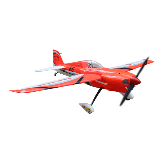
Code : SEA 114
ASSEMBLY MANUAL
Specifications:
Wingspan---------------80.5 in--------------(204.5cm)
Wing area---------------1069.5--------------sq.ins (69 sq.dm)
Weight-------------------11.9-13.2 lbs------(7.6kg)
Length-------------------64.3 in -------------(163.4 cm)
Engine/Motor size---------------------------50-60cc gasoline
Radio---------------------5 channels with 6 servos
1
Advertisement
Table of Contents

Related Manuals for Seagull Models NEMESIS


Summary of Contents for Seagull Models NEMESIS
- Page 1 Code : SEA 114 ASSEMBLY MANUAL Specifications: Wingspan---------------80.5 in--------------(204.5cm) Wing area---------------1069.5--------------sq.ins (69 sq.dm) Weight-------------------11.9-13.2 lbs------(7.6kg) Length-------------------64.3 in -------------(163.4 cm) Engine/Motor size---------------------------50-60cc gasoline Radio---------------------5 channels with 6 servos...
-
Page 2: Kit Contents
You will find that most of the work has been done for you already. The motor mount has been fitted and the hinges are pre-installed. Flying the NEMESIS is simply a joy. This instruction manual is designed to help you build a great flying aeroplane. Please read this manual throughly before starting assembly of your NEMESIS Use the parts listing be- low to indentify all parts. -
Page 3: Additional Items Required
KIT CONTENTS HINGING THE AILERON NEMESIS SEA114 Note : The control surfaces, including the ailer- ons, elevators, and rudder, are prehinged with 1. Fuselage hinges installed, but the hinges are not glued in 2. Wing set (2) place. It is imperative that you properly adhere 3. - Page 4 Instruction Manual. N E M E S I S After both ailerons are securely hinged, firmly grasp the wing panel and aileron to make sure the hinges are securely glued and cannot be pulled out. Do this by care- fully applying medium pressure, trying to separate the aileron from the wing panel.
- Page 5 Place low-tack tape 1/32 inch (1mm) INSTALL THE AILERONS from the control horn slot. This will pre- CONTROL HORN vent epoxy from getting on the control surface when the control horns are glued Locate the aileron and flap control horns. in place.
-
Page 6: Installing The Aileron Servos
Instruction Manual. N E M E S I S Epoxy Minimum servo spec. Torque : 6.0V: 192.4 oz-in (13.8 kg-cm) Before the epoxy fully cures, remove 7.4V: 350.0 oz-in (25.2 kg-cm) the tape from around the control horn. This will allow the epoxy to flow around the control horn, creating a small filet Because the size of servos differ, you between the control horn and surface for... - Page 7 Apply 2-3 drops of thin C/A to each of the mounting holes. Allow the C/A to cure without using accelerator. C/A glue C/A glue Remove the string from the wing at the servo location and use the tape to attach it to the servo extension lead.
-
Page 8: Aileron Pushrod Installation
Instruction Manual. N E M E S I S AILERON PUSHROD INSTALLATION - Please study images below. 75mm M3 lock nut M3 clevis Set the aileron hatch in place and use a Phillips screw driver to install it with four wood screws. - Page 9 INSTALLING LANDING GEAR Locate items necessary to install Sprin Landing Gear. Collar. M3x4mm.
- Page 10 Instruction Manual. N E M E S I S...
-
Page 11: Installing The Fuselage Servos
THROTTLE SERVO ARM INSTALLING THE FUSELAGE SERVOS INSTALLATION Because the size of servos differ, you Install adjustable servo connector in the may need to adjust the size of the precut servo arm as same as picture below: opening in the mount. The notch in the sides of the mount allow the servo lead to pass through. -
Page 12: Installing The Switch
Instruction Manual. N E M E S I S INSTALLING THE SWITCH Install the switch into the precut hole in the side, in the fuselage. 3/32” Hole. INSTALLING THE STOPPER ASSEMBLY Using a modeling knife, carefully cut off the rear portion of one of the 3 nylon tubes leaving 1/2”... -
Page 13: Fuel Tank Installation
FUEL TANK INSTALLATION Vent tube. Fuel pick up tube. You should mark which tube is the vent and which is the fuel pickup when you attach fuel tubing to the tubes in the stopper. Once the tank is installed inside the fuselage, it may be difficult to determine which is which. -
Page 14: Mounting The Engine
Instruction Manual. N E M E S I S Vent tube. Fuel pick up tube. Fuel fill tube. Connect the lines from the tank to the engine and muffler. The vent line will connect to the muffler and the line from the clunk tothe carburetor. - Page 15 5x90mm...
- Page 16 Instruction Manual. N E M E S I S 180mm Ignition Modude...
- Page 17 Reinstall the servo horn by sliding the connector over the pushrod wire. Center COWLING the throttle stick and trim and install the servo horn perpendicular to the servo - Please see below pictures. center line. Move the throttle stick to the closed po- Tape the cowl to the fuselage using low- sition and move the carburetor to closed.
- Page 18 Instruction Manual. N E M E S I S With the muffler, needle valve, and spark/ glow plug removed from the engine, slide the cowl in place over the engine. Tem- porarily install the propeller and spinner in order to fid the exact location of the cowl.
- Page 19 Because of the size of the cowl, it may be nec- essary to use a needle valve extension for the high speed needle valve. Make this out of suf- ficient length 1.5mm wire and install it into the end of the needle valve. Secure the wire in place by tightening the set screw in the side of the needle valve.
- Page 20 Instruction Manual. N E M E S I S - Motor: 360 - 6000 Watts - Propeller: 24x10 ~ 25x12 - ESC: 160A - 200A - 12S Lipo Attach the electric motor box to the fire- wall centered with the cross lines drawn on the electric motor box and firewall.
- Page 21 Then, use 8mm drill bit to enlarge the holes on the electric motor box. 6x35mm Attach the motor to the front of the electric motor box using four 4mm blind nut, four M6x35mm hex head bolts to se- cure the motor. Please see picture shown. Blind nut 6mm.
-
Page 22: Installing The Spinner
Instruction Manual. N E M E S I S 180mm Balsa stick Epoxy Battery Attach the speed control to the side of INSTALLING THE SPINNER the motor box using two-sided tape and tie wraps. Connect the appropriate leads from the speed control to the mo- - Install the spinner backplate, propeller tor. - Page 23 Epoxy. HINGING THE ELEVATOR Glue the elevator hinges in place using tthe same techniques as shown in images below. INSTALL ELEVATOR CONTROL HORN Fiberglass control horn.
-
Page 24: Hinging The Rudder
Instruction Manual. N E M E S I S Elevator fiberglass control horn Epoxy Epoxy HINGING THE RUDDER Glue the top three rudder hinges in place using the same techniques used to Epoxy hinge the elevator. The lower hinge will be glued when the fin/rudder assembly is attached to the fu- selage. - Page 25 INSTALL RUDDER CONTROL HORN Repeat steps to install the rudder control horn as same as steps done for elevator. Fiberglass control horn. Epoxy...
- Page 26 Instruction Manual. N E M E S I S INSTALLING THE HORIZONTAL STABILIZER Using a ruler and a pen, locate the cen- terline of the horizontal stabilizer, at the trailing edge, and place a mark. Use a tri- angle and extend this mark, from back to front, across the top of the stabilizer.
- Page 27 Epoxy When you are sure that everything is With the stabilizer held firmly in place, aligned correctly, mix up a generous use a pen and draw lines onto the stabi- amount of 30 Minute Epoxy. Apply a thin lizer where it and the fuselage sides meet. layer to the top and bottom of the stabi- Do this on both the right and left sides lizer mounting area and to the stabilizer...
- Page 28 Instruction Manual. N E M E S I S INSTALLING VERTICAL STABILIZER Hinge Using a modeling knife, remove the covering from over the precut hinge slot cut into the lower rear portion of the fu- selage. This slot accepts the lower rudder hinge.
- Page 29 When you are sure that everything is aligned correctly, mix up a generous amount of Flash 30 Minute Epoxy. Ap- ply a thin layer to the mounting slot and to bottom of the vertical stabilizer mounting area. Apply epoxy to the bot- tom and top edges of the filler block and to the lower hinge also.
- Page 30 Instruction Manual. N E M E S I S ELEVATOR PUSHROD INSTALLATION Locate items necessary to install elevator pushrod. RUDDER PUSHROD INSTALLATION Locate items necessary to install rudder pushrod. Elevator pushrods assembly as pictures below. Rudder pushrods assembly as pictures below.
- Page 31 MOUNTING THE TAIL WHEEL Locate items necessary to install tail wheel. 3x25mm 3x20mm...
- Page 32 Instruction Manual. N E M E S I S INSTALLATION PILOT AND CANOPY Locate items necessary to install pilot, seats.
- Page 33 Epoxy 70mm Wing bolt C/A glue ATTACHMENT WING - FUSELAGE Attach the aluminium tube into fuselage. 4x20mm Wing tube...
- Page 34 Instruction Manual. N E M E S I S BALANCING An important part of preparing the air- craft for flight is properly balancing the model. 1) Attach the wing panels to the fuselage. Make sure to connect the leads from the aileron to the appropriate leads from the receiver.
-
Page 35: Control Throws
CONTROL THROWS Ailerons: Rudder: High Rate : High Rate : Up : 30 mm Right : 40 mm Down : 30 mm Left : 40 mm Low Rate : 135mm Low Rate : Up : 20 mm Right : 30 mm Down : 20 mm Left : 30 mm Elevator:... -
Page 36: Flight Preparation
A) Plug in your radio system per the 2) Check every bolt and every glue manufacturer’s instructions and turn eve- joint in the NEMESIS to ensure that eve- rything on. rything is tight and well bonded. B) Check the elevator first. Pull back on the elevator stick. - Page 37 If you have any queries, or are interested in our products, please feel free to contact us Factory : 12/101A - Hamlet 4 - Le Van Khuong Street - Dong Thanh Ward - Hoc Mon District - Ho Chi Minh City - Viet Nam. Office : 62/8 Ngo Tat To Street - Ward 19 - Binh Thanh District - Ho Chi Minh City - Viet Nam Phone : 848 - 86622289 or 848- 36018777...
Need help?
Do you have a question about the NEMESIS and is the answer not in the manual?
Questions and answers