Table of Contents
Advertisement
Quick Links
Brushless DC Motor Control
Installation, Maintenance and Parts Manual
DORNER MFG. CORP.
P.O. Box 20 • 975 Cottonwood Ave.
Hartland, WI 53029-0020 USA
851-738 Rev. A
For other service manuals visit our website at:
www.dorner.com/service_manuals.asp
INSIDE THE USA
TEL: 1-800-397-8664
FAX: 1-800-369-2440
OUTSIDE THE USA
TEL: 262-367-7600
FAX: 262-367-5827
Advertisement
Table of Contents

Related Manuals for Dorner 62M050PLBDDEN


Summary of Contents for Dorner 62M050PLBDDEN
- Page 1 Brushless DC Motor Control Installation, Maintenance and Parts Manual DORNER MFG. CORP. INSIDE THE USA OUTSIDE THE USA P.O. Box 20 • 975 Cottonwood Ave. TEL: 1-800-397-8664 TEL: 262-367-7600 Hartland, WI 53029-0020 USA FAX: 1-800-369-2440 FAX: 262-367-5827 For other service manuals visit our website at: www.dorner.com/service_manuals.asp...
-
Page 2: Table Of Contents
For 3 Phase (230 Volt) Controllers: ......9 Introduction The Dorner Limited Warranty applies. A CAUTION Dorner reserves the right to make changes at any time Some illustrations may show guards without notice or obligation. removed. DO NOT operate equipment without Dorner has convenient, pre-configured kits of Key Service guards. -
Page 3: Warnings - General Safety
KEEP OFF CONVEYORS. Climbing, sitting, walking or riding on conveyor will cause severe injury. SEVERE HAZARD! DANGER • Dorner cannot control the physical installation and application of conveyors. Taking protective measures is the responsibility of the user. • When conveyors are used in conjunction... -
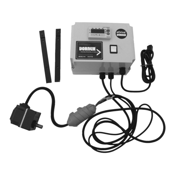
Page 4: Product Description
Product Description Brushless DC Motor Control Figure 1 Dorner’s Brushless DC Motor Control (Figure 1) are DC motor speed controllers for Standard and Heavy Load VFD gearmotors. Typical Components Mode indicator LEDs The illuminating LED indicates the current operation mode. -
Page 5: Specifications
10.4 62M010ESBDDEN 0.25 0.200 See Control 62M005ESBDDEN 0.25 0.200 See Control Controllers Dorner Model Input Input Input Volt Input Output Reversing Type Number Phase Watts Amps 63MBD11B60 63MBD23B60 63MBD11B200 63MBD23B200 Brushless DC Motor Control 851-738 Rev. A Dorner Mfg. Corp. -
Page 6: Installation
Hex Head Screws, M4 x 16 mm (4x) T-Bar Hex Head Screws, M6 x 16 mm (2x) Figure 4 Slide controller to its desired mounting location along conveyor and tighten both screws. Brushless DC Motor Control Dorner Mfg. Corp. 851-738 Rev. A... -
Page 7: Stand Mounting
Partially thread controller mounting bar (Figure controller. 7, item 1) to top t-nut with screw (Figure 7, item 2). Figure 7 Figure 7 Slide controller to its desired mounting location and tighten both screws. Brushless DC Motor Control 851-738 Rev. A Dorner Mfg. Corp. -
Page 8: For 1 Phase (115 Volt) Controllers
9, item 4) to N (Figure 9, item 5) wires on controller. Connect motor plugs (Figure 10, item 1) and (Figure 10, item 2). Figure 10 Figure 8 Figure 10 Brushless DC Motor Control Dorner Mfg. Corp. 851-738 Rev. A... -
Page 9: For 3 Phase (230 Volt) Controllers
Install outer cord cover (Figure 12, item 1) over inner cord cover (Figure 12, item 2). Figure 12 Figure 12 Twist covers (Figure 13, item 1) together, as shown. Figure 14 Figure 13 Figure 13 Brushless DC Motor Control 851-738 Rev. A Dorner Mfg. Corp. - Page 10 Figure 19 Figure 16 Secure wires by tightening grip (Figure 16, item 6). Install case cover (Figure 14, item 2). with four plastic cover screws (Figure 14, item 1). Figure 19 Brushless DC Motor Control Dorner Mfg. Corp. 851-738 Rev. A...
-
Page 11: For Remote On/Off Signal
Remove access plug (Figure 21, item 1). Figure 21 Figure 21 Open controller by loosening four plastic cover screws (Figure 21, item 2), and removing controller case cover (Figure 21, item 3). Brushless DC Motor Control 851-738 Rev. A Dorner Mfg. Corp. -
Page 12: External Input Signals
Figure 23 Input signal common (0 V) Upper stage Lower stage Jumper X3 to Common Input signal common ON: Clockwise rotation ON: Counterclockwise rotation OFF: Stop OFF: Stop Figure 23 Brushless DC Motor Control Dorner Mfg. Corp. 851-738 Rev. A... -
Page 13: Operation
(Figure 25, item 3) until “SPd1” (Figure 26, item 1) is displayed. Press set (Figure 26, item 2) again. “SPd1” When purchased with a gearmotor, Dorner configures (Figure 26, item 1) will blink and correct speed (Figure Variable Speed VFD Controllers as follows: 26, item 3) will be displayed. - Page 14 Pressing and holding the key for 3 seconds or more will increase or decrease the value successively Figure 29 Figure 32 10. Press MODE to switch to the monitor mode. Figure 29 Brushless DC Motor Control Dorner Mfg. Corp. 851-738 Rev. A...
-
Page 15: Set Motor Direction
(Gearhead Ratio) x (Drive Sprocket Teeth) (4.28 Factor) x (Pulley Dia.) x (3.14) x (Driven Sprocket Teeth) (15) x (44) (4.28) x (0.104) x (3.14) x (22) • Conveyor gear ratio = 21.5 Brushless DC Motor Control 851-738 Rev. A Dorner Mfg. Corp. - Page 16 37, item 3) to confirm the new setting. Press MODE to switch to the monitor mode. The r/min LED or m/min LED will illuminate according to the specified display mode. Brushless DC Motor Control Dorner Mfg. Corp. 851-738 Rev. A...
-
Page 17: Setting Speed While Motor Is Running
Press SET (Figure 41, item 3) to confirm the selection. The display will blink. Figure 39 Press SET (Figure 40, item 1). The new speed will be set to the operation data digitally. Figure 40 Figure 40 Brushless DC Motor Control 851-738 Rev. A Dorner Mfg. Corp. -
Page 18: Notes
Notes Brushless DC Motor Control Dorner Mfg. Corp. 851-738 Rev. A... -
Page 19: Service Parts
Service Parts NOTE For replacement parts other than those shown in this section, contact an authorized Dorner Service Center or the factory. Key Service Parts and Kits are identified by the Performance Parts Kits logo . Dorner recommends keeping these parts on hand. -
Page 20: Return Policy
RMA will automatically close 30 days after being issued. To get credit, items must be new and undamaged. There will be a return charge on all items returned for credit, where Dorner was not at fault. It is the customer’s responsibility to prevent damage during return shipping.
Need help?
Do you have a question about the 62M050PLBDDEN and is the answer not in the manual?
Questions and answers