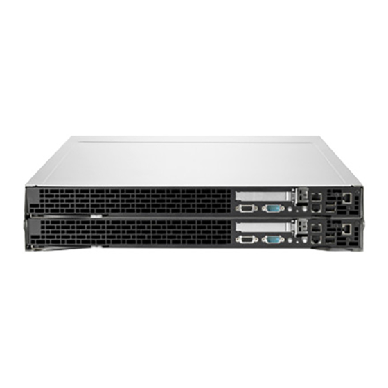
HP ProLiant SL160z G6 Maintenance And Service Manual
Hide thumbs
Also See for ProLiant SL160z G6:
- Specifications (64 pages) ,
- Overview (42 pages) ,
- Specification (33 pages)

Related Manuals for HP ProLiant SL160z G6


Summary of Contents for HP ProLiant SL160z G6
- Page 1 All manuals and user guides at all-guides.com HP ProLiant SL160z G6 Server Maintenance and Service Guide Part number 571293-005 Fifth edition March 2011...
- Page 2 © Copyright 2010, 2011 Hewlett-Packard Development Company, L.P. The information contained herein is subject to change without notice. The only warranties for HP products and services are set forth in the express warranty statements accompanying such products and services. Nothing herein should be construed as constituting an additional warranty.
-
Page 3: Table Of Contents
Illustrated parts catalog ........................16 Mechanical components ..........................16 System components ........................... 20 HP Contact Information ..........................23 Before You Contact HP ..........................24 Removal and Replacement Procedures ....................25 Hardware Configuration Tools ........................25 Hardware Configuration Information ......................25 Electrostatic Discharge Information ...................... - Page 4 All manuals and user guides at all-guides.com Power-on Self-Test (POST) ........................... 72 POST Error Indicators ........................... 72 POST Errors Message Definition ......................73 POST Related Troubleshooting ....................... 74 Physical and Operating Specifications ....................75 System Unit .............................. 75 Index ..............................78 Contents 4...
-
Page 5: Customer Self Repair
If during the diagnosis period HP (or HP service providers or service partners) identifies that the repair can be accomplished by the use of a CSR part, HP will ship that part directly to you for replacement. There are two categories of CSR parts: •... - Page 6 Centre d'assistance technique HP. Dans les documents envoyés avec la pièce de rechange CSR, HP précise s'il est nécessaire de lui retourner la pièce défectueuse. Si c'est le cas, vous devez le faire dans le délai indiqué, généralement cinq (5) jours ouvrés. La pièce et sa documentation doivent être retournées dans l'emballage fourni.
- Page 7 In caso di necessità si può richiedere l'assistenza telefonica di un addetto del centro di supporto tecnico HP. Nel materiale fornito con una parte di ricambio CSR, HP specifica se il cliente deve restituire dei componenti. Qualora sia richiesta la resa ad HP del componente difettoso, lo si deve spedire ad HP entro un determinato periodo di tempo, generalmente cinque (5) giorni lavorativi.
- Page 8 Flexibilität beim Austausch defekter Bauteile zu ermöglichen. Wenn HP (oder ein HP Servicepartner) bei der Diagnose feststellt, dass das Produkt mithilfe eines CSR-Teils repariert werden kann, sendet Ihnen HP dieses Bauteil zum Austausch direkt zu. CSR-Teile werden in zwei Kategorien unterteilt: •...
- Page 9 HP podrá cobrarle por el de sustitución. En el caso de todas sustituciones que lleve a cabo el cliente, HP se hará cargo de todos los gastos de envío y devolución de componentes y escogerá la empresa de transporte que se utilice para dicho servicio.
- Page 10 Optioneel: Onderdelen waarvoor reparatie door de klant optioneel is. Ook deze onderdelen zijn ontworpen voor reparatie door de klant. Als u echter HP verzoekt deze onderdelen voor u te vervangen, kunnen daarvoor extra kosten in rekening worden gebracht, afhankelijk van het type garantieservice voor het product.
- Page 11 CSR de reposição se a peça com defeito deve ser devolvida à HP. Nos casos em que isso for necessário, é preciso enviar a peça com defeito à HP dentro do período determinado, normalmente cinco (5) dias úteis. A peça com defeito deve ser enviada com a documentação correspondente no material de transporte fornecido.
- Page 12 All manuals and user guides at all-guides.com Customer self repair 12...
- Page 13 All manuals and user guides at all-guides.com Customer self repair 13...
- Page 14 All manuals and user guides at all-guides.com Customer self repair 14...
- Page 15 All manuals and user guides at all-guides.com Customer self repair 15...
-
Page 16: Illustrated Parts Catalog
Optional—Parts for which customer self repair is optional. These parts are also designed for customer self repair. If, however, you require that HP replace them for you, there may or may not be additional charges, depending on the type of warranty service designated for your product. - Page 17 All manuals and user guides at all-guides.com Mandatory: Obligatoire—Pièces pour lesquelles la réparation par le client est obligatoire. Si vous demandez à HP de remplacer ces pièces, les coûts de déplacement et main d'œuvre du service vous seront facturés. Optional: Facultatif—Pièces pour lesquelles la réparation par le client est facultative. Ces pièces sont également conçues pour permettre au client d'effectuer lui-même la réparation.
- Page 18 Optional: Opcional—Peças cujo reparo feito pelo cliente é opcional. Essas peças também são projetadas para o reparo feito pelo cliente. No entanto, se desejar que a HP as substitua, pode haver ou não a cobrança de taxa adicional, dependendo do tipo de serviço de garantia destinado ao produto.
- Page 19 All manuals and user guides at all-guides.com Illustrated parts catalog 19...
-
Page 20: System Components
All manuals and user guides at all-guides.com System components Item Description Spare Part Number Customer Self Repair System Fan 576898-001 Mandatory SATA cable 1 576895-001 Mandatory SATA cable 2 576895-001 Mandatory PCIe X16 riser card 536654-001 Optional Memory Module Mandatory DIMM 1GB PC3-10600E 501539-001 Mandatory... - Page 21 Optional—Parts for which customer self repair is optional. These parts are also designed for customer self repair. If, however, you require that HP replace them for you, there may or may not be additional charges, depending on the type of warranty service designated for your product.
- Page 22 All manuals and user guides at all-guides.com Mandatory: Obbligatorie—Parti che devono essere necessariamente riparate dal cliente. Se il cliente ne affida la riparazione ad HP, deve sostenere le spese di spedizione e di manodopera per il servizio. Optional: Opzionali—Parti la cui riparazione da parte del cliente è facoltativa. Si tratta comunque di componenti progettati per questo scopo.
-
Page 23: Hp Contact Information
Optional: Opcional—Peças cujo reparo feito pelo cliente é opcional. Essas peças também são projetadas para o reparo feito pelo cliente. No entanto, se desejar que a HP as substitua, pode haver ou não a cobrança de taxa adicional, dependendo do tipo de serviço de garantia destinado ao produto. -
Page 24: Before You Contact Hp
All manuals and user guides at all-guides.com ○ Call 1-800-HP-INVENT (1-800-474-6836). This service is available 24 hours a day, 7 days a week. For continuous quality improvement, calls may be recorded or monitored. ○ If you have purchased a Care Pack (service upgrade), call 1-800-633-3600. For more information about Care Packs, refer to the HP website at http://www.hp.com/. -
Page 25: Removal And Replacement Procedures
All manuals and user guides at all-guides.com Removal and Replacement Procedures This chapter provides subassembly/module-level removal and replacement procedures for the HP ProLiant SL160z G6 server. Review the specifications of a new component before installing it to make sure it is compatible with the server. -
Page 26: Pre-Installation Procedure
Press the power button on the front panel to turn on the server. NOTE: The HP ProLiant SL160z G6 server supports up to 2 750-W power supply units, but 1 power supply only supports 2 nodes of the sever and 2 power supply supports 4 nodes of the sever. -
Page 27: Symbols On Equipment
All manuals and user guides at all-guides.com WARNING: To reduce the risk of personal injury from hot surfaces, allow the drives and the internal system components to cool before touching them. CAUTION: Do not operate the server for long periods with the access panel open or removed. Operating the server in this manner results in improper airflow and improper cooling that can lead to thermal damage. -
Page 28: Powering Down The Server
All manuals and user guides at all-guides.com This symbol indicates the presence of a hot surface or hot component. If this surface is contacted, the potential for injury exists. WARNING: To reduce the risk of injury from a hot component, allow the surface to cool before touching. -
Page 29: Cable Management
All manuals and user guides at all-guides.com Figure 1 Removing the top cover To reinstall the top cover: Align the top cover to the chassis and then slide it towards the front panel to position it into place. Fasten the two rear screws to secure the top cover to the chassis. Figure 2 Reinstalling the top cover Cable Management... -
Page 30: Cable Connections
All manuals and user guides at all-guides.com • When folding a flat ribbon cable, never fold to a sharp crease. Sharp creases may damage the wires. • Some flat ribbon cables come pre-folded. Never change the folds on these cables. •... -
Page 31: Hard Drives
All manuals and user guides at all-guides.com Table 2 Node Cable connections Cable System Board Designator Internal USB connector Node USB SATA cable connector Node SATA1 SATA cable connector Node SATA2 SATA SGPIO cable Node SGPIO connector Table 3 AC power board connection Cable System Board Designator RJ45 cable connector... - Page 32 All manuals and user guides at all-guides.com To install a Hard Drive: Unlock the HDD carrier latch. Rotate the HDD carrier handle up. Insert the HDD carrier and align the four pins. Rotate the HDD carrier handle down and then lock the HDD carrier latches. Figure 5 Installing the hard drive assembly To remove hard drive:...
-
Page 33: System Board Configuration
System Board Configuration Processor HP ProLiant SL160z G6 Server, with 2 nodes, supports four-processor operation. With two processors installed, each node supports boot functions through the processor installed in processor socket 1. However, if processor 1 fails, the system automatically boots from processor 2 and provides a processor failure message. - Page 34 All manuals and user guides at all-guides.com CAUTION: Place heat sink down in an upright position with the thermal patch facing upward. Do not let the thermal patch touch the work surface. Figure 8 Removing the Heat Sink assembly IMPORTANT: If the heat sink has been removed for any reason on a previously installed processor, it is critical that you apply more thermal interface material to the integrated heat spreader on the processor to ensure proper thermal bonding between the processor and the heat sink.
- Page 35 All manuals and user guides at all-guides.com Figure 10 Removing the processor Carefully rotate the tool, and then push in and release the tabs to secure the processor in the tool. Figure 11 Securing the processor CAUTION: To avoid damage to the processor, do not touch the bottom of the processor, especially the contact area.
- Page 36 All manuals and user guides at all-guides.com To install the new processor: Carefully insert the processor into the processor installation tool. Handle the processor by the edges only, and do not touch the bottom of the processor, especially the contact area. Figure 12 Inserting the processor Removal and Replacement Procedures 36...
- Page 37 All manuals and user guides at all-guides.com Be sure the tool is oriented correctly. Align the processor installation tool with the socket, and then install the processor. THE PINS ON THE SYSTEM BOARD ARE VERY FRAGILE AND EASILY DAMAGED. Figure 13 Installing the processor CAUTION: THE PINS ON THE SYSTEM BOARD ARE VERY FRAGILE AND EASILY DAMAGED.
- Page 38 All manuals and user guides at all-guides.com Figure 14 Removing the processor installation tool Close the processor socket retaining bracket and the processor locking lever. CAUTION: Be sure to close the processor socket retaining bracket before closing the processor locking lever. The lever should close without resistance. Forcing the lever closed can damage the processor and socket, requiring system board replacement.
- Page 39 Apply the thermal grease compound to the CPU contact surface. CAUTION: HP recommends using Shin-Etsu X-23-7783D thermal grease compound for your ProLiant server. Apply all the grease to the top of the processor in the following pattern to insure even distribution.
-
Page 40: Memory
All manuals and user guides at all-guides.com Figure 17 Installing the heat sink Memory HP ProLiant SL160z G6 server has thirty-two DIMM slots that support up to 256 GB maximum system memory. You must adhere to the following guidelines when adding or replacing memory modules: •... - Page 41 If the holding clips do not close, the module is not inserted correctly. NOTE: The ProLiant SL160z G6 server supports up to 32 memory modules. Install them in the DIMM slots starting from the DIMM 1 slot.
-
Page 42: Pci Expansion Cards
All manuals and user guides at all-guides.com PCI Expansion Cards System Board PCI Expansion Slots There are one X16 and one X4 PCIe Riser slots on the system boards. Figure 21 PCIe expansion slot location on 160 system board Item Component Component Function... - Page 43 All manuals and user guides at all-guides.com Figure 22 PCIe Riser Card X16 Connectors Location Figure 23 PCIe Riser Card X4 Connectors Location • Single-Slot PCIe riser card (x16 slot) To remove the PCIe riser card with the bracket: Loosen the screw securing the riser card bracket to the chassis. Pull the riser card away together with the bracket.
- Page 44 All manuals and user guides at all-guides.com Figure 24 Removing the PCIe riser card To remove the X16 riser card from the bracket: Remove the two screws securing the riser card to the bracket. Pull the riser card away from the bracket. Figure 25 Removing the PCIe riser card To install the PCIe X16 riser card to the bracket:...
- Page 45 All manuals and user guides at all-guides.com Figure 26 Installing PCIe riser card to the bracket To install the riser card with the bracket into the motherboard: Align the riser card connector with the slot on the motherboard and then insert the assembly into the slot.
- Page 46 All manuals and user guides at all-guides.com Figure 28 Remove the PCIe X4 Cage To remove the PCIe X4 riser card: Remove the screw that secures the riser card to the cage. Pull the PCIe card out and away from the PCIe X4 cage. Figure 29 Removing the Riser Card X4 To install the PCIe riser card to the cage:...
- Page 47 All manuals and user guides at all-guides.com Figure 30 Reinstalling the PCIe riser card X4 To install the PCIe X4 cage: Align the riser card cage beside the PCIe X4 connecter on the main board Install and tighten the two screws to secure the riser card cage to the chassis. Figure 31 Reinstalling the PCIe Riser Card X4 To remove the PCIe card:...
-
Page 48: System Battery
All manuals and user guides at all-guides.com Figure 32 Removing the PCIe card To install the PCIe card: Open the PCIe latch. Remove PCIe card or blank. Push the PCIe card into riser card connector. Close PCIe latch. Install screws. Figure 33 Installing the PCIe card System Battery... - Page 49 System battery location WARNING: Note the following reminders when replacing the system battery: • Replace the battery with the same type as the battery recommended by HP. Use of another battery may present a risk of fire or explosion. •...
-
Page 50: System Board Removal And Replacement Procedure
All manuals and user guides at all-guides.com Figure 35 Replacing the battery System Board Removal and Replacement Procedure To remove the system board: Remove the tray with the system board: Press the tray latch to release the tray handle. Rotate the tray handle to disengage the power connector. Pull the tray assembly out of the chassis. - Page 51 All manuals and user guides at all-guides.com Figure 37 Removing the 160 system board from the tray To replace the 160 system board: Put the system board in the chassis. The nine screw holes on the chassis should align with the system board.
-
Page 52: Power Supply Unit (Psu)
All manuals and user guides at all-guides.com Figure 39 Installing the tray with system board into the chassis Power Supply Unit (PSU) Located on the rear panel of the server power supply is a standard auto ranging 750watt PSU with PFC (power factor correction) function. - Page 53 All manuals and user guides at all-guides.com Slide the power supply into the power supply bay until it snaps into place. Figure 41 Installing the Power supply (1) Figure 42 Installing the power supply (2) To remove the power supply: Press the blue colored handle.
-
Page 54: System Fan
All manuals and user guides at all-guides.com Figure 43 Removing the power supply System Fan The server can support either 3 or 4 system fans located at the chassis’ rears fan cage. Fan 1 is optional. You can refer to Fan option Installation instructions for details. The figure below identifies the system fans by their device number and shows their corresponding cable connections. - Page 55 All manuals and user guides at all-guides.com A new system fan can be installed to allow the server to operate properly in case a default system fan becomes defective. To remove the system fan: Disconnect the fan cable from its corresponding board connector. Lift the system fan away from the chassis.
-
Page 56: Connectors, Switches, And Leds
This chapter contains illustrations and tables identifying and describing the connectors, switches, buttons, and LED indicators located on the front panel, rear panel, system board and hard drives of the HP ProLiant SL160z G6. Connectors and Components Front Panel Components... -
Page 57: Rear Panel Components
All manuals and user guides at all-guides.com Item Description Power Button Rear panel components Figure 48 Rear panel components Item Description RJ45 port Power supply 2 Power supply 1 UID LED Connectors, Switches, and LEDs 57... -
Page 58: System Board Components
All manuals and user guides at all-guides.com System board components Figure 49 System board components Item Designator Description Serial Port (COM1) VGA port USB PORT NIC Port J21,J22,J79; MEMORY DIMM CONN J23,J24,J78; J25,J26,J77 UID BUTTON IPMI CONN PCIE-X4 LP RISER SLOT PCIE-X16 FH/FL RISER SLOT A Jumper TPM CONN... -
Page 59: Jumpers -Password And Chassis Id
If you suspect a TPM board failure, leave the TPM installed and remove the system board. Contact an HP authorized service provider for a replacement system board and TPM board. Jumpers –Password and Chassis ID Password (J50) and chassis ID (J45) jumpers. -
Page 60: Led Indicators
All manuals and user guides at all-guides.com LED Indicators This section contains illustration and descriptions of internal and external status LED indicators located on the: • Front panel • Rear panel These LED indicators aid in problem diagnosis by indicating the status of system components and operations of the server. - Page 61 All manuals and user guides at all-guides.com Table 5 Health LED indicator status Components Status Description System is off and there is no failure prior to system power off Figure 51 UID LED indicator location Table 6 Type table name here Components Status Descriptions...
-
Page 62: Rear Panel Led Indicators
All manuals and user guides at all-guides.com Figure 52 Power LED indicator location Table 7 Power/system health LED indicator status Component Status Description Power LED indicator for Node 1 Steady green The server is operating normally. Steady Amber The server is system off or in hibernation with A/C power. - Page 63 All manuals and user guides at all-guides.com Figure 53 LAN/LED indicator location Table 8 LAN/LED indicator states Item Component Status Description LAN activity status LED indicator Flashing green Ongoing network data activity. No network data activity or no connection. LAN network speed LED Steady green The LAN connection is using a GbE indicator...
-
Page 64: Diagnostic Tools And Setup Utilities
If the server is already turned on, save your data and exit all open applications, then restart the server. When the HP logo is displayed during POST, press F10 into BIOS Setup Utility. If you fail to press F10 before POST is completed, you will need to restart the server. -
Page 65: Navigating Through The Setup Utility
All manuals and user guides at all-guides.com Navigating through the Setup Utility Use the keys listed in the legend bar on the right of the Setup screen to navigate through the various menu and submenu screens of the Setup Utility. Table 9 lists these legend keys and their respective functions. -
Page 66: Setup Utility Menu Bar
All manuals and user guides at all-guides.com Figure 54 Setup Utility General Help screen Press F1 to get the general help message box. Setup Utility Menu Bar The BIOS Setup Utility provides a menu bar with the menu selections. The menu bar choices are described in the topics below. - Page 67 All manuals and user guides at all-guides.com • View CPU type / CPU speed /CPU physical count information. • View System memory size. • View System serial number. • View MAC address for the embedded NIC. • Set Server Asset Tag. •...
- Page 68 All manuals and user guides at all-guides.com • Super IO Configuration–You can use this screen to select options for the Super I/O settings. Use the up and down <Arrow> keys to select an item. Use the <Plus> and <Minus> keys to change the value of the selected option.
- Page 69 All manuals and user guides at all-guides.com • Watchdog Configuration –Select Watchdog Configuration in the left frame of the screen and press<enter> to go to the submenu for that item. That will display POST Watchdog Timer Action, BMC Watch Dog Time Out; you can change the default value. •...
- Page 70 All manuals and user guides at all-guides.com • Change Admin Password --- Allows you to access and change all settings in the Setup Utility. The administrator password allows you to configure access for system users. To set a new administrator password: In the Security screen, select a set password field - Change Admin Password, and then press Enter.
-
Page 71: Bios Update
All manuals and user guides at all-guides.com Exit Menu Figure 61 Exit menu of the BIOS Setup Utility Use this menu to save changes or discard changes. When you save and exit, the server reboots. • Save Changes and Exit --- Save the changes you have made and exit the BIOS Setup Utility. (You can also press F10 key.) •... -
Page 72: Clear Cmos
POST. The number of tests displayed depends on the configuration of the server. During POST you can: • Press ESC to skip the HP logo and go to POST boot progress display system summary screen. • Press F7 to display the Boot menu. •... -
Page 73: Post Errors Message Definition
All manuals and user guides at all-guides.com POST Errors Message Definition Whenever a non-fatal error occurs during POST, an error message describing the problem appears onscreen. These error messages are displayed in normal video (white text on black background), and show the details of the error. -
Page 74: Post Related Troubleshooting
All manuals and user guides at all-guides.com Table 10 POST error message Error: BMC Not Responding Refresh timer test failed Password check failed CMOS Memory Size Wrong Floppy Controller Failure RAM R/W test failed CMOS Battery Low Insufficient Runtime space for MPS data. System may operate in PIC or Non-MPS mode. -
Page 75: Physical And Operating Specifications
All manuals and user guides at all-guides.com Physical and Operating Specifications This chapter provides physical and operating specifications for the HP ProLiant SL160z G6 server. Specifications include: System Unit Table 11 Hardware Specifications Item Components Processor socket Intel 1366pin FCLGA... - Page 76 All manuals and user guides at all-guides.com Table 11 Hardware Specifications Item Components Status LED indicators Front panel • Power/system health status • UID status • NIC activity • LAN activity Rear Panel • LAN link status • Power/system health status •...
- Page 77 All manuals and user guides at all-guides.com Table 13 Environmental Specifications Item Description Thermal output (maximum operating) 392 W/hr Acoustic emissions LWad: 6.7 Bels Normal configuration (operating at room temperature) LWad: 6.7 Bels (Idle at room temperature) Table 14 Hot-Plug Power Supply Specifications Item Description Dimensions (H x W x D)
-
Page 78: Index
All manuals and user guides at all-guides.com Index hard drives, 32 memory, 41 AC power PCI expansion cards, 43 power-down procedures, 28 power supply unit, 53 processor, 34 battery references, 25 replacement warnings, 50 system battery, 49 BIOS Setup Utility system fan, 55 accessing, 65 top cover, 28... - Page 79 All manuals and user guides at all-guides.com Power-On Self Test POST error indicators, 73 improper airflow POST related troubleshooting, 75 caution, 26 recoverable POST errors, 74 processor LAN controller, 76 applying thermal grease, 40 LED indicators installing, 40 LAN, 63 removing, 36 Power/system health, 62 Processor heat sink...
- Page 80 All manuals and user guides at all-guides.com front panel, 57 spare part number, 16 rear panel, 58 Tray with system board System Unit removing, 51 specifications, 76 replacing, 52 thermal solution, 77 warnings top cover battery replacement, 50 reinstalling, 29 PSU replacement, 53 removing, 28 warranty, 5...
Need help?
Do you have a question about the ProLiant SL160z G6 and is the answer not in the manual?
Questions and answers