
Related Manuals for Detex Advantex 10 Series


Summary of Contents for Detex Advantex 10 Series
- Page 1 Maintenance Manual Models Included: 10 Series Advantex Wide Stile Rim Exit Devices. 40 Series Advantex Narrow Stile Rim Exit Devices.
-
Page 2: Table Of Contents
Table of Contents Component Page Device Component Identification….…..…………………………..……………….3 Uninstalling Device ……………….………………………….……………..……………….4 Door Strikes……….…….…………….………………………………………..……………….8 Center Case.……..……..…….………………….……………………………………………11 Pushpad..……..…….…….……..…….………………………………………………………13 Filler Plate………..……..………………………………………………………………………14 Extrusion and Wrap…….……………………………………………………………….…14 End Caps.……….….……………………………………………………………………………15 Lubrication……...…………………….……………………………………………………….16 Page 2 of 17... -
Page 3: Device Component Identification
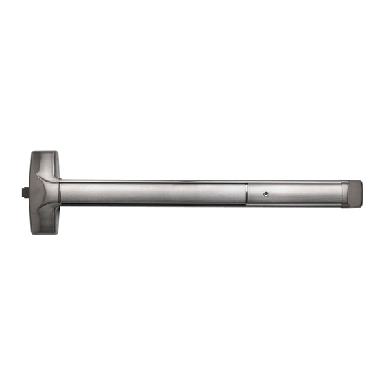
DEVICE COMPONENT IDENTIFICATION Door Frame Door Center Case with Cover Extrusion & Wrap End Cap Strike Pushpad Assembly Hex Dogging Key Filler Plate with HD Outside Trim Function, 08D shown. 10 Series device shown with hex dogging option, LHR and outside trim option installed. Page 3 of 17... -
Page 4: Uninstalling Device
UNINSTALLING DEVICE To facilitate maintenance procedures, the device must be removed from the door. Verify the functionality of the device before removing any hardware. Look for any misaligned components and missing or loose screws. Record the current status of the device, as this could help plan a maintenance program that will keep the device working properly and extend its service life. - Page 5 STEP 2. Remove 4 screws used on center case cover and pull it away from device to access the mount plate screws (2). Remove 2 screws used on end cap in order to access the end bracket mounting screws (2). Although the surface finish is strong and durable, handle the parts with care to avoid scratches or contamination from harsh chemicals during the service process.
- Page 6 STEP 4. Push Pushpad and hold device with both hands. While keeping pushpad pushed, pull at hinge side end away from door (1), swinging the device against center case mount plate to disengage tabs and allowing device to pull free from mounting plate (2). Place device on a flat surface covered with a clean, soft cloth to avoid scratches or surface contamination.
- Page 7 STEP 6. Uninstall device components, position device on its back and slide out filler plate and rub strip from housing. Filler plate may include wires; if so, these should be handled carefully to avoid damaging electronic connections. RUB STRIP FILLER PLATE STEP 7.
-
Page 8: Door Strikes
STEP 9. (SHOWN FOR REFERENCE ONLY) This step concludes the disassembling of a 10/40 Advantex series rim exit device. (2X) 10-32 x1/4” PPH DTX #PP-5207-104 DTX #PP-5067-10 (2X) #10 STAR LOCK WASHER DTX #PP-5067-10 (2X) PUSHPAD END CAP ADV DTX #104617-1 (MULTIPLE FINISHES AVAILABLE) CHASSIS LATCH END... - Page 9 SHIM DOOR FRAME STRIKE LOCK SCREW MOUNT SCREW OPTION 2. 98 strike kit DTX #100855-1. Strike model 98 is a half mortise mounted with 2 screws and is shimmed as needed to allow proper alignment with the latch of the device. It includes a shield that helps prevent tampering and is typically used on glass doors.
- Page 10 OPTION 3. 94 strike kit DTX #102212-1. Strike model 94 is mounted with 2 screws and is shimmed as needed to allow proper alignment with the latch of the device. It is designed to be used on double-door applications with one side inactive. Kit includes all parts shown below; additional mount screws are included (not shown) to accommodate varying door construction.
- Page 11 CENTER CASES Advantex 10 and 40 Series exit devices can be built with either a Wide Stile Center Case Cover (10 Series) or a Narrow Stile Center Case Cover (40 Series). DTX # MODEL DESCRIPTION 100196-X COVER WIDE RIM 100311-X COVER NARROW RIM DTX #100196-X 10 SERIES SHOWN Advantex 10 and 40 Series exit devices can be built in a variety of configurations.
-
Page 12: Center Case
OPTION 2. Center Case Subassembly: EE OPTIONS DTX #104023-X, used as follows: EE FEATURE PWA DTX # MODEL DESCRIPTION 104023-2 CENTER CASE ADV 10 EE 104023-3 CENTER CASE ADV 40 EE DTX #104023-2 10 SERIES SHOWN OPTION 3. Center Case Subassembly: LX/LXV OPTION DTX #103786-3, used as follows: EE/ FEATURE PWA DTX # MODEL DESCRIPTION... -
Page 13: Pushpad
DTX # MODEL DESCRIPTION 103806-1 BP2 RIM 98 103806-1W BP2 RIM 98 W 103806-2 BP1 RIM 99 ADDITIONAL SCREWS 103806-2W BP1 RIM 99 W REQ’D WHEN DOOR IS 103806-3 BP2 RIM 99 HURRICANE RATED 103806-3W BP2 RIM 99 W 103806-16 BP2 RIM 94 103806-16W BP2 RIM 94 W... -
Page 14: Filler Plate
FILLER PLATE Filler plates are held in place between the pushpad and the end cap; no screws or hooks are needed to hold the filler plates in place. Like the pushpad, filler plates have a variety of lengths and configurations depending on the application of the device. DTX # 100711-X CD SHOWN DTX # LENGTH... - Page 15 There are two models of end caps for Advantex devices: the EC1 (ramped end cap) and the EC2 (flush end cap). Each model has an additional FC (flex conduit) option. All end caps are mounted with 2 screws into the end bracket. OPTION 1.
-
Page 16: Lubrication
LUBRICATION All Detex devices are delivered properly lubricated with a multipurpose synthetic grease. It is strongly recommended that all mechanical parts and surfaces of the device be periodically lubricated, inspected, and tested. Before applying lubrication: 1) Remove/Clean any foreign material from area to be lubricated. - Page 17 Customer Service : 830-629-2900 Website: www.detex.com Detex Corporation. 302 Detex Drive, New Braunfels, Texas 78130-3045 Page 17 of 17...
Need help?
Do you have a question about the Advantex 10 Series and is the answer not in the manual?
Questions and answers