Advantech ICR-2431 User Manual
Lte industrial router
Hide thumbs
Also See for ICR-2431:
- User manual (44 pages) ,
- Hardware manual (44 pages) ,
- Start manual (9 pages)
Table of Contents
Advertisement
Quick Links
Advertisement
Table of Contents

Related Manuals for Advantech ICR-2431


Summary of Contents for Advantech ICR-2431
- Page 1 LTE Industrial Router ICR-2431 USER MANUAL...
- Page 2 ICR-2431 c 2021 Advantech Czech s.r.o. No part of this publication may be reproduced or transmitted in any form or by any means, electronic or mechanical, including photography, recording, or any information storage and retrieval system without written consent. Information in this manual is subject to change without notice, and does not represent a commitment on the part of Advantech.
- Page 3 Information, notice – Useful tips or information of special interest. GPL licence Source codes under GPL licence are available at https://icr.advantech.cz/source-code address. Advantech Czech s.r.o., Sokolska 71, 562 04 Usti nad Orlici, Czech Republic Document No. MAN-0058-EN, revision from September 3, 2021. Released in the Czech Republic.
-
Page 4: Table Of Contents
ICR-2431 Contents 1 Product Oveview 1.1 Product Introduction ....... . . - Page 5 ICR-2431 Appendix D: Related Documents...
- Page 6 ICR-2431 List of Figures Access to the Internet from LAN ......Backed up Access to the Internet .
- Page 7 ICR-2431 List of Tables Hardware Overview of the Router ......Order Codes Overview ....... .
-
Page 8: Product Oveview
1. Product Oveview 1.1 Product Introduction Industrial cellular router ICR-2431 is designed for wireless communication in the mobile networks that make use of traditional cellular technologies. The primary purpose of this router is its use in the Category 4 (Cat.4) services on the cellular LTE network. -
Page 9: Product Usage
ICR-2431 1.2 Product Usage The router is primarily intended for these four basic situations: I. Access to the Internet from LAN Figure 1: Access to the Internet from LAN II. Backed up access to the Internet (from LAN) Figure 2: Backed up Access to the Internet... -
Page 10: Using Vpn Tunnel
ICR-2431 III. Secure networks interconnection or using VPN Figure 3: Using VPN Tunnel IV. Serial Gateway Figure 4: Serial Gateway... -
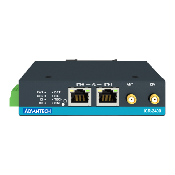
Page 11: Hardware Overview
ICR-2431 1.3 Hardware Overview The router case preview is shown in Figure 5. A short description of hardware parts of the router is listed in Table 1, including the links to the chapters with a detailed description. Figure 5: Hardware Overview of the Router... -
Page 12: Order Codes
ICR-2431 Continued from previous page Item/Caption Type Description Button to reboot the router or to restore the default configuration, see Chapter 2.8. ETH0 RJ45 100 MB Ethernet connection for the first LAN, see Chap- ter 2.3. ETH1 RJ45 100 MB Ethernet connection for the second LAN, see Chapter 2.3. -
Page 13: Package Contents
ICR-2431 1.5 Package Contents The standard set of router includes items listed in the following table: Item# Figure Q’ty Description Router 1 pcs Wall mounting clip with screws 1 set 6-pin terminal block for power sup- ply, digital input and digital output (de-... -
Page 14: Product Dimensions
ICR-2431 1.6 Product Dimensions For the dimensions of the product see the figures below. Note that all sizes are measured in millimeters. Figure 5: Product Dimensions – Front View Figure 6: Product Dimensions (with wall mounting clip) – Top View... -
Page 15: Mounting Recommendations
ICR-2431 1.7 Mounting Recommendations The router can be placed: • on a flat surface, • on a wall using the wall mounting clip (see Chapter 1.8), • on a DIN rail EN 60715 with the metal DIN rail clip (see Chapter 1.9) -
Page 16: Wall Mounting
ICR-2431 1.8 Wall Mounting The wall mounting clip is supplied with the router as standard accessories. The router can be screwed to a wall (or another surface) using the wall mounting clip. There are two wholes on the clip with a diameter of 4 millimeters. For detailed information about the mounting dimensions see Figure in Chapter 1.6. -
Page 17: Din Rail Mounting
ICR-2431 1.9 DIN Rail Mounting The DIN rail clip is not supplied with the router as standard accessories, but it can be ordered by the order code BB-DIN-ICR32. The DIN rail clip is suitable for a DIN rail according to EN 60715 standard only. The default position of the clip is shown in Figure 8. -
Page 18: Product Label
ICR-2431 1.10 Product Label An example of the product label, with all the information printed on it, is in the figure below. Figure 10: Label Example... -
Page 19: Hardware Functionality
ICR-2431 2. Hardware Functionality See Chapter for the product hardware overwiew. Table lists a short description of the hardware, including the links to the chapters with a detailed description. 2.1 SIM Card Slots Slots for two SIM cards are located on the right panel of the router under a metal cover. It is necessary to insert an activated SIM card, to work properly. -
Page 20: Cellular Antennas
ICR-2431 2.2 Cellular Antennas Main (ANT) and diversity (DIV) antennas can be connected to the router using the SMA connectors located on the front panel. Do not run the router without connected cellular antenna connected to the main antenna connectors as the energy from the transmission is effectively reflected by the open end and can damage the equipment. -
Page 21: Power Supply
ICR-2431 2.4 Power Supply The pins of power supply are physically connected to the 6-pin terminal block panel socket located on the left panel. The connection of power supply is shown in Figure and described in Table 3. Figure 7: Connection of Power Supply... -
Page 22: I/O Port Interfaces
ICR-2431 2.5 I/O Port Interfaces The maximum length of wires connected to the I/O ports is 3 meters to meet the EMC immunity conditions. The pins of I/O interface are physically connected to the 6-pin terminal block panel socket located on the left panel. The pinout of one binary input and one binary output is shown in Figure and described in Table 4. -
Page 23: Serial Interfaces
ICR-2431 2.6 Serial Interfaces The pins of RS232 and RS485 serial interfaces are physically connected to the 7-pin ter- minal block panel socket located on the left panel. The pinout of this connector is described in Figure and in Table 5, resp. Table 6. -
Page 24: Led Status Indication
ICR-2431 2.7 LED Status Indication There are LED indicators on the front panel of the router to provide router status informa- tion. Moreover, ETH connector, has two additional LEDs providing information about the port status. Caption Color State Description Green... -
Page 25: Reset Functions
ICR-2431 2.8 Reset Functions The RST button on the front panel can be used in three different situations: • Reboot the router: Hold the RST button for less than 4 seconds, the router will be restarted. • Factory reset – restore the default configuration: Hold the RST button for more than 4 seconds. -
Page 26: Overview Of Router Reboot And Reset
ICR-2431 Action Router behavior Trigger events – options Reboot Turns off and then • Disconnect and reconnect the power. turns on the router • Send text reboot via SMS to SIM card number put in your router (your phone number has to be authorized –... -
Page 27: First Use
ICR-2431 3. First Use 3.1 Powering up the Router The router will start up when a power supply is connected to it. By default, the router will automatically log on to the default APN of the inserted SIM card. The DHCP server will assign an addresses to the devices connected through the Ethernet port ETH0. -
Page 28: Router's Web Interface
ICR-2431 Figure 13: Router’s Web Interface A detailed description of the router settings in the web interface can be found in the configura- tion manual of the router. -
Page 29: Technical Specifications
ICR-2431 4. Technical Specifications 4.1 Basic Parameters Router parameters Temperature range Operating ◦ C to +75 ◦ Storage C to +85 ◦ ◦ Humidity Operating 5 to 95 % relative humidity non condensing Storage 5 to 95 % relative humidity non condensing... -
Page 30: Standards And Regulations
ICR-2431 4.2 Standards and Regulations The router complies with the following standards and regulations: Standards and regulations Radio EN 301 511, EN 301 908-1 13.1.1, EN 301 908-2, EN 301 908-13 EN 301 489-1, EN 301 489-52, EN 61000-4-2, EN 61000-4-3,... -
Page 31: Type Tests And Environmental Conditions
ICR-2431 4.3 Type Tests and Environmental Conditions Phenomena Test Description Test levels EN 61000-4-2 Contact discharge ± 6 kV (crit. A) Air discharge ± 8 kV (crit. A) RF field AM EN 61000-4-3 Enclosure 10 V/m (crit. A) modulated (80 – 6000 MHz) -
Page 32: Parameters Of Cellular Module
ICR-2431 4.4 Parameters of Cellular Module Technical parameters of cellular module LTE parameters LTE: LTE Cat.4, 3GPP Rel. 11 FDD frequencies: B28A (700 MHz), B20 (800 MHz), B8 (900 MHz), B7 (2600 MHz), B3 (1800 MHz), B1 (2100 MHz) TDD frequencies: B41 (2500 MHz), B40 (2300 MHz),... -
Page 33: Parameters Of I/O Ports
ICR-2431 4.5 Parameters of I/O Ports Electrical characteristics of the binary inputs are in Table 13. Status of the binary input is reported in the GUI on General Status page or can be retrieved in the Shell via io get bin0 command. -
Page 34: Appendix A: Troubleshooting
ICR-2431 Appendix A: Troubleshooting If you cannot connect to the router from your PC, your network card may be configured in such a way that it is not possible to connect to the router. Take one or more of the following steps in order to solve the problem: •... - Page 35 ICR-2431 • Go to "System Log" page in "Status" section and observe where the error occurs. ✍ I cannot connect from the Internet to the device behind the router. I have NAT enabled. • The device’s gateway has to be configured so it points to the router.
- Page 36 ICR-2431 ✍ Serial communication is not working. • Verify that the router model supports serial communications. Also verify the serial communication settings. To do so, open the router’s configuration menu via the web browser, select the appropriate "Expansion Port" from "Configuration" part of the menu and verify the settings.
-
Page 37: Appendix B: Customer Support
ICR-2431 Appendix B: Customer Support Customer Support for Europe Advantech Czech s.r.o. Sokolska 71 562 04, Usti nad Orlici, Czech Republic Phone: +353 91 792444 Fax: +353 91 792445 E-mail: iiotcustomerservice@advantech.eu Web: www.advantech.com Customer Support for NAM Advantech B+B SmartWorx... -
Page 38: Appendix C: Regulatory & Safety Information
ICR-2431 Appendix C: Regulatory & Safety Information Safety Notices Please, observe the following instructions: • The router must be used in compliance with all applicable international and national laws and in compliance with any special restrictions regulating the utilization of the router in prescribed applications and environments. - Page 39 ICR-2431 Product Disposal Instructions The WEEE (Waste Electrical and Electronic Equipment: 2012/19/EU) directive was in- troduced to ensure that electrical/electronic products are recycled using the best available recovery techniques in order to minimize impact on the environment. This product contains high quality materials and components which can be recycled.
- Page 40 ICR-2431 Appendix D: Related Documents Advantech Czech: Start Guide (QSG-0011-EN) Advantech Czech: ICR-2000, ICR-2400, ICR-2500, ICR-2600 – Configuration Manual (MAN-0059-EN) Product related documents can be obtained on Engineering Portal at www.icr.advantech.cz address.
- Page 41 ICR-2431 Hereby, Advantech Czech s.r.o. company declares that the radio equipment narrated in this user’s guide is in compliance with EU Directive 2014/53/EU. The full text of the EU Declaration of Conformity is available at the following internet address: icr.advantech.cz/eudoc...
Need help?
Do you have a question about the ICR-2431 and is the answer not in the manual?
Questions and answers