
Related Manuals for Microm HM 355 S


Summary of Contents for Microm HM 355 S
- Page 1 Rotary Microtome HM 355 S ROTARY MICROTOME HM 355 S-2 INSTRUCTION MANUAL MICROM International GmbH Robert-Bosch-Str. 49 69190 Walldorf 387841 - English...
- Page 2 Rotary Microtome HM 355 S MICROM International GmbH Robert-Bosch-Str. 49 D- 69190 Walldorf 387841 - English...
- Page 3 This MICROM product is warranted against defects in material and workmanship for a period of 1 year. Parts which prove to be defective during the warranty period will be repaired or replaced free of charge by MICROM International GmbH. No other warranty is expressed or implied.
- Page 4 MICROM serial number: ............... Please check the MICROM Ser. No. on the type plate, which is placed on the rear side of your instrument and enter this number here. This way, questions and service can be handled faster.
-
Page 5: Table Of Contents
PART 2 INTRODUCTION Description Rotary Microtome HM 355 S Accessories 2-2-1 Standard equipment 2-2-2 Additional equipment (optional) Technical data Rotary Microtome HM 355 S PART 3 OPERATING INSTRUCTIONS Setting up the microtome Initial turn-on 3-2-1 Operating panel Display and key functions... - Page 6 Rotary Microtome HM 355 S Menu 3-8-1 Selection of operating modes 3-8-2 Date and time 3-8-3 Display mode 3-8-4 Turning off the function "Retraction" 3-8-5 Language selection for the display Setting the cutting speed 3-10 Push-in handwheel handle 3-11 Adapters for specimen clamping...
- Page 7 Rotary Microtome HM 355 S PART 6 CONDITIONS FOR THE TRANSPORTATION OF THE INSTRUMENT Returning the instrument for repair and routine maintenance Disposal of the instrument after final shutdown MICROM International GmbH Robert-Bosch-Str. 49 D- 69190 Walldorf 387841 - English...
- Page 8 Rotary Microtome HM 355 S EC Certificate of Conformity Name and address of MICROM International GmbH the manufacturer: Robert-Bosch-Straße 49 D-69190 Walldorf Product designation: Rotary Microtome Type reference: HM 355 S -2 Notification to Competent Authorities: These medical devices have been registered with the German authority as “Microtomes”...
- Page 9 Rotary Microtome HM 355 S Hans Heid Walldorf, 16 June 2005 Managing Director MICROM International GmbH Robert-Bosch-Str. 49 D- 69190 Walldorf 387841 - English...
-
Page 10: Part 1 Important Information
Rotary Microtome HM 355 S PART 1 IMPORTANT INFORMATION WARNING SIGNALS AND SYMBOLS The installation and routine use of the HM 355 S is easy and safe if the instructions in this manual are being observed. Note: Special instructions regarding operation of the instrument. - Page 11 Please observe the following general precautions during operation of this instrument. Failure to comply with these precautions violates safety standards and the intended use of the instrument. MICROM International GmbH is not liable for misuse of the instruments and failure to comply with basic safety requirements.
- Page 12 Rotary Microtome HM 355 S HAZARD OF RADIOACTIVE RADIATION When working with radioactive specimens observe all applicable radiation safety procedures. When working with radioactive contaminated material, appropriate safety and disinfection measures must be carried out. According to the rules and regulations concerning the handling of radioactive contaminated material of the respective laboratory, safety clothing (e.g.
-
Page 13: Intended Use
Rotary Microtome HM 355 S INTENDED USE The Rotary Microtome HM 355 S from MICROM International GmbH is a universal heavy duty microtome for especially sophisticated paraffin, and hard sectioning techniques in biology, medicine and industry. Only skilled or specially trained personnel must operate the microtome, i.e. clamping the specimen, trimming and first cuts, sectioning and transferring sections onto a slide. -
Page 14: Part 2 Introduction
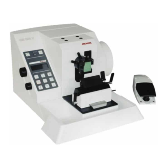
The HM 355 S will cut sections in a range from 0,5 µm up to 100 µm. For the protection of knife and specimen, the instrument retracts the specimen at the end of the cut. If desired, the function <retraction> can be turned off. - Page 15 Rotary Microtome HM 355 S Total overview Fig. 1 MICROM International GmbH Robert-Bosch-Str. 49 D- 69190 Walldorf 387841 - English...
-
Page 16: Accessories
Rotary Microtome HM 355 S ACCESSORIES 2-2-1 STANDARD EQUIPMENT The Rotary Microtome HM 355 S is supplied with the following accessories: 1 Standard section waste tray 1 Hex head wrench 6 mm 1 Cover 1 Para Gard, 100 ml 1 Instruction manual... - Page 17 Rotary Microtome HM 355 S Cat. no. Segment arc 715050 Universal specimen holder 715060 2-2-2-3 OPTICAL ACCESSORIES Large field magnifier, 220 V 760160 Large field magnifier, 120 V 760170 Stereomicroscope Stemi 2000 755210 Adapter for Stemi 2000 532090 KL 1500 with ring illumination...
- Page 18 Rotary Microtome HM 355 S 2-2-2-5 ADDITIONAL ACCESSORIES Fast freezing unit K 34 100 V/50 - 60 Hz 115 V/60 Hz 230 V/50 Hz 240 V/50 Hz Section transfer system STS 100 V/50 - 60 Hz 115 V/60 Hz 230 V/50 Hz...
- Page 19 Rotary Microtome HM 355 S TECHNICAL DATE HM 355 S Microtome: Section thickness range .......... 0,5 - 100 µm Resolution..........0,5 µm from 0,5 - 5 µm ..............1 µm from 5 - 20 µm ..............2 µm from 20 - 30 µm ..............
-
Page 20: Part 3 Operating Instructions
Rotationsmikrotom HM 355 S PART 3 OPERATING INSTRUCTIONS SETTING UP THE MICROTOME • Cut through the bands around the carton. • Open the carton. • Remove the accessories. • On the lower rear side of the instrument, there is a recessed grip to lift or carry the microtome. -
Page 21: Initial Turn-On
Rotationsmikrotom HM 355 S INITIAL TURN-ON Note: The kind of the used examination materials and all special conditions for their processing, pre-treatment and, if necessary, storage as well as instrument controls correct safe operation responsibility of the operator. The operator is also responsible for special equipment and materials and/or reagents for the operation of the instrument. - Page 22 Rotationsmikrotom HM 355 S • Connect the plug of the foot pedal cable into the outlet (fig. 3.6) and tighten the swivel nut. Note: If the foot pedal is not connected, there is the operating mode emergency stop (see part 3-6-7).
-
Page 23: Operating Panel
Rotationsmikrotom HM 355 S 3-2-1 OPERATING PANEL The operating elements of the panel are clearly arranged and allow for a safe operation of the instrument. • The operating panel can be removed from the instrument and used stand-alone. Fig. 5 MICROM International GmbH Robert-Bosch-Str. -
Page 24: Display And Key Functions
Rotary Microtome HM 355 S DISPLAY AND KEY FUNCTIONS 3-3-1 SETTING CUTTING WINDOW • Turn the handwheel so that the lower edge of the specimen is positioned slightly above the knife edge • Briefly press the button (fig. 6.1) to set the upper limit of the cutting window. -
Page 25: Handwheel Brake
Rotary Microtome HM 355 S 3-3-3 HANDWHEEL BRAKE The microtome is equipped with a handwheel brake. This way, unintended movements of the specimen holder and knife carrier are avoided. This reduces the danger of being injured while adjusting specimen clamp and knife carrier. -
Page 26: Emergency Stop
Rotary Microtome HM 355 S 3-3-4 EMERGENCY STOP To quickly eliminate danger, the microtome has two "emergency stop" devices. Caution: In case danger arises from cutting drive, push the "emergency stop"! The hand emergency stop button (fig. 9.1) is placed on the right side of the microtome below the handwheel. -
Page 27: Indication Of Cutting Processes
Rotary Microtome HM 355 S 3-3-5 INDICATION OF CUTTING PROCESSES In the lower line of the display information about the sectioning status can be seen. • Press the "scroll button" (fig. 11.1), to show the various functions one after the other on the display. - Page 28 Rotary Microtome HM 355 S 3-3-5-3 REMAINING TRAVEL TO FRONT END POSITION TRIM= 30 FINE= 9 This value shows the distance in microns, which is left for sectioning (fig. 14.3). If the specimen holder is in the back end position, REM.TRAV.
-
Page 29: Setting Section Thickness And Trimming Thickness
Rotary Microtome HM 355 S SETTING SECTION THICKNESS AND TRIMMING THICKNESS • required section trimming thicknesses are set by means of the control knob (fig. 16.1), which is placed on the side part of the operating panel. • To choose between section thickness and trimming thickness, press the control knob (fig. -
Page 30: Trimming And First Cuts
Rotary Microtome HM 355 S 3-4-1 TRIMMING AND FIRST CUTS After the specimen and the knife are adjusted, further gradual feed for trimming can be carried out using the function "trimming". For different sectioning series, deeper layers of the specimen can be reached with the function "trimming". -
Page 31: Fine Feed
Rotary Microtome HM 355 S 3-4-2 FINE FEED After having adjusted knife and specimen as well as having trimmed the specimen, sectioning can be started. • Press the control knob (fig. 20.1) to select the FINE section thickness setting. •... -
Page 32: Cutting Movement And Retraction
Rotary Microtome HM 355 S CUTTING MOVEMENT AND RETRACTION The cutting movement of the microtome is generated by turning the handwheel or use the motorized cutting drive. • To start the cutting movement of the microtome, turn the handwheel. •... -
Page 33: Motorized Cutting Drive
Rotary Microtome HM 355 S MOTORIZED CUTTING DRIVE Sectioning can be carried out either manually by turning the handwheel or by means of a motorized cutting drive. • The cutting movement can either be released by pressing the button START/STOP (fig. -
Page 34: Specimen Feed
Rotary Microtome HM 355 S SPECIMEN FEED 3-7-1 COARSE FEED AND SPEED FOR COARSE FEED After changing the specimen or moving the knife or knife carrier, it is necessary to adjust the specimen to the knife edge again. This can easily be done by means of the specimen coarse feed and the defined trimming values. - Page 35 Rotary Microtome HM 355 S MENU 3-8-1 SELECTION OF OPERATING MODES For the motorized cutting movement of the microtome, the following operating modes are available: - interval stroke - single stroke - multi stroke - continuous stroke • Press the menu button (fig. 28.1).
- Page 36 Rotary Microtome HM 355 S INTERVAL STROKE • Press the menu button (fig. 28.1). • In the submenu "Mode" select the function Mode Inter. "Interval" (fig. 21) via the knob (fig. 30.1) • Now a gradual approach between specimen Select: Turn knob and cutting edge is possible.
- Page 37 Rotary Microtome HM 355 S CONTINUOUS STROKE • Press the menu button (fig. 28.1). • In the submenu "Mode" select the function "Cont."(fig. 34) via the knob (fig. 31.1 • Mode : Cont. To start a continuous cutting cycle, use the foot pedal or press the START/STOP button (fig.
- Page 38 Rotary Microtome HM 355 S 3-8-2 DATE AND TIME Via this menu, the current time as well as the current date can be set in the instrument. • Press the menu button (fig. 35.1). The sub- menu (fig. 36) appears on the display.
- Page 39 Rotary Microtome HM 355 S 3-8-3 DISPLAY MODE NORMAL Section thickness display, Here the display mode can be selected. You can FINE is currently active choose between the NORMAL and the LARGE display mode. • The normal display mode (fig. 37) shows the selected fine and trim section thickness with additional status indications at the same time.
- Page 40 Rotary Microtome HM 355 S 3-8-4 TURNING OFF THE FUNCTION "RETRACTION" If desired, the function "retraction" can be turned off. RETRACTION R:ON • Press the menu button (fig. 41.1). Select: Turn knob • Select submenu "Retraction" via the knob (fig.
- Page 41 Rotary Microtome HM 355 S 3-8-5 SELECTING THE INDICATED LANGUAGE The sectioning information on the display can be Language ENGLISH shown alternatively in different languages. Select: Turn knob German English Confirm: Press French Spanish Italian Fig. 43 • Press the menu button (fig. 44.1).
- Page 42 Rotary Microtome HM 355 S SETTING THE CUTTING SPEED The desired cutting speed is set continuously on the control knob (fig. 46.3) and shown on display with values from 0 - 99. To save time, the return travel speed is enhanced in relation to the cutting speed, especially for slow cutting speeds.
- Page 43 Rotary Microtome HM 355 S 3-10 PUSH-IN HANDWHEEL HANDLE For safer working with the motorized cutting drive, the handwheel handle (fig. 49) can be pushed in. • To lock the handwheel handle, first take the handle on its outer bush and push it inside until it locks.
- Page 44 Rotary Microtome HM 355 S 3-11 ADAPTERS FOR SPECIMEN CLAMPING 3-11-1 ADAPTER, NON-ORIENTING This adapter serves non-orienting fastening of the specimen clamps directly on the cylinder of the instrument. 3-11-2 ADAPTER, ORIENTING, SPECIMEN ORIENTATION • Using the orienting adapter fasten the specimen clamps on the cylinder head.
- Page 45 Rotary Microtome HM 355 S 3-11-3 CHANGING AND/OR CLAMPING SPECIMEN CLAMPS The available specimen clamps are all clamped or removed in the same way. • To change the specimen clamping system, press clamping lever (fig. 51.1) downwards and pull it sideways.
- Page 46 Rotary Microtome HM 355 S 3-11-4 READJUSTING SPECIMEN CLAMPS Frequent use of the clamping lever (fig. 52.1) can lead to the fact that the specimen clamps cannot be clamped optimally anymore. If the necessary readjustments are not carried out, it might even be possible that the specimen clamp cannot be clamped.
- Page 47 Rotary Microtome HM 355 S 3-12 SPECIMEN CLAMPING To clamp specimens, different specimen clamping systems are available. With the orienting adapter it is simple to align the specimen properly in relation to the knife. 3-12-1 UNIVERSAL CASSETTE CLAMP The universal cassette clamp (fig. 54) represents a quick change system.
- Page 48 Rotary Microtome HM 355 S 3-12-3 STANDARD SPECIMEN CLAMP The standard specimen clamp (fig. 56) is used for rectangular and square paraffin and plastic blocks. • Insert the specimen against the fixed jaw (fig. 56.2) first. • Then turn the knob (fig. 56.3) to tighten jaw (fig.
- Page 49 Rotary Microtome HM 355 S 3-12-4 INSERT FOR ROUND SPECIMEN, V-INSERT AND V-DISTANCE PIECE To cut round specimens, the insert for round specimens (fig. 57.A) with defined diameters of 6, 15 and 25 mm (special sizes on request) or the V- insert (fig.
- Page 50 However, it is possible to turn in Z-axis 60° in either direction. • Then insert the foil clamp. • According to the various specimens, it might be helpful to use in addition MICROM's sandwich supporting material (cat. 176010) on the right and left side between specimen and clamping jaw.
- Page 51 Rotary Microtome HM 355 S 3-12-6 SEGMENT ARC AND UNIVERSAL SPECIMEN HOLDER The segment arc and universal specimen holder are highly suitable for the clamping of small specimens embedded in plastic (fig. 59). • The specimen is inserted in the holder (fig.
- Page 52 Rotary Microtome HM 355 S 3-13 KNIFE CARRIERS Hazard of hand injuries: Due to moving parts in connection also with the microtome knife, a danger area arises, which might lead to hand injuries in case of non-compliance with the safety features of the microtome and when disregarding the instruction manual.
- Page 53 Rotary Microtome HM 355 S Using high profile blades: When using high profile blades, first remove the spacer strip (fig. 60.3). • For this, turn the clamping lever (fig. 60.7) to the front until the stop. • The press the stop pin into the knife carrier and further turn the clamping lever (fig.
- Page 54 Rotary Microtome HM 355 S 3-13-2 DISPOSABLE BLADE CARRIER E Inserting the blade: • The disposable blade carrier E is designed to take all commercially available high and low profile blades. • Insert the blade into the slot behind the clamping plate (fig.
- Page 55 Rotary Microtome HM 355 S Clearance angle adjustment: • The clearance angle between cutting edge and specimen can be shifted and adjusted to the requirements of the tissue to be sectioned. • Loosen the clamping lever (fig. 61.3) on the right side of the knife carrier and move the upper part of the knife carrier (fig.
- Page 56 Rotary Microtome HM 355 S 3-13-3 KNIFE CARRIER C Inserting the knife: • To insert the knife, the clamping screws (fig. 62.3) must be unscrewed slightly so the knife can be pushed in from the side. • The height of the knife is adjusted with the two knurled nuts (fig.
- Page 57 Rotary Microtome HM 355 S Moving the knife carrier on the console: • Loosen the clamping lever (fig. 62.5) on the left side of the knife carrier to move the carrier forwards and backwards on the dovetail guide. • This allows a rough adjustment of knife and specimen.
- Page 58 Rotary Microtome HM 355 S 3-13-4 READJUSTING KNIFE CARRIERS Frequent use of the clamping levers can lead to the fact that the knife carriers cannot be clamped optimally anymore. If the necessary readjustments are not carried out, it might even be possible that the knife carriers cannot be clamped anymore.
- Page 59 Rotary Microtome HM 355 S 3-14 SECTION WASTE TRAY WITH INTEGRATED ARM REST The section waste tray with integrated arm rest can easily be cleaned. • The section waste tray surrounds the knife carrier area and allows non-tiring working with the microtome.
- Page 60 Rotary Microtome HM 355 S 3-15 MEMORY FUNCTION The memory function is used to quickly find again the same position for the first cuts. This function can only be used on condition that blocks, which have been embedded in the same molds, are cut.
- Page 61 Rotary Microtome HM 355 S 3-16 LARGE FIELD MAGNIFIER The large field magnifier (fig. 68.1) is for looking at section production. • The light is connected to the power outlet with the power cord (fig. 68.2) and turned on and off with the switch (fig.
- Page 62 Rotary Microtome HM 355 S PART 4 WORKING WITH THE MICROTOME Hazard of hand injuries: Due to moving parts in connection also with the microtome knife, a danger area arises, which might lead to hand injuries in case of non-compliance with the safety features of the microtome and when disregarding the instruction manual.
- Page 63 As the facet has a divergence from the knife main surface of approx. 5°, the difference is approx. 5°. Set the correct angle on MICROM instruments at 10°. Fig. 72 MICROM International GmbH Robert-Bosch-Str.
- Page 64 Rotary Microtome HM 355 S HOW TO AVOID MALFUNCTIONS Specimen preparation: • When preparing specimens, be sure that a suitable embedding medium, fixation, dehydration and infiltration time are chosen. Specimen temperature: • Sectioning carried ambient temperature (excluding frozen sections). •...
- Page 65 Rotary Microtome HM 355 S POSSIBLE SOURCES OF ERRORS – CAUSE AND REMOVAL Problem Cause Removal − − Thick-thin-sections Blunt knife/blade. Move knife and/or insert a new one. − − Knife angle, therefore, clearance angle unfavorable clearance angle. adjustments, until an optimal angle can be found.
- Page 66 Rotary Microtome HM 355 S Problem Cause Removal − − Cutting drive motor cannot be Emergency stop button Deactivate the emergency stop started activated. button. − − Foot pedal not connected. Connect foot pedal or interlock plug. Note: In case of malfunctions and/or service work, please turn off the instrument and contact your local dealer.
- Page 67 Rotary Microtome HM 355 S PART 5 MAINTENANCE AND CARE CLEANING AND CARE Cleaning and care of the microtome should be carried out daily. Please proceed as follows: • Lock the handwheel. • Remove the knife from the knife carrier. Clean it and store it in a knife case! •...
- Page 68 Rotary Microtome HM 355 S • Before starting sectioning, instrument, knife carrier and section waste tray should be treated with a commercially available paraffin repellent. Note: This medium considerably reduces the adhesive force of paraffin waste on the individual parts of the microtome.
- Page 69 Rotary Microtome HM 355 S REPLACEMENT WORK Replacing the fuses: The two fuses of the instrument are placed on the rear side of the instrument beside the main switch (fig. 73.1). • To replace the two fuses, turn off the main switch of the instrument and unplug it.
- Page 70 Repair or maintenance work are normally carried out at the site of installation. If this is not possible for some specific reasons, the instrument can be returned to MICROM. The contact address can be found at the beginning of this instruction manual. •...
- Page 71 Rotary Microtome HM 355 S For transportation outside closed buildings, please observe the following measures: • Turn off the main switch of the instrument. • Remove knife or blade and store it in a safe place. • Remove the section waste tray.
Need help?
Do you have a question about the HM 355 S and is the answer not in the manual?
Questions and answers