
Related Manuals for Eloma MULTIMAX 6-11


Summary of Contents for Eloma MULTIMAX 6-11
- Page 1 MULTIMAX Sizes: 6-11, 10-11, 20-11, 20-21 Energy type: Gas and electric Translation of the original operating instructions Subject to technical changes. Read carefully before use. Keep safe for future use.
- Page 2 Legal notice Eloma GmbH . Innovative Koch- & Backtechnik Otto-Hahn-Str. 10 82216 Maisach Germany Phone: +49 (0) 8141 395-188 Fax: +49 (0) 8141 395-130 Chef's forum and user tips User hotline: +49 (0) 35023 63887 Website: www.eloma.com Service Service hotline: +49 (0) 35023 63888 Device type: ……………...
-
Page 3: Table Of Contents
Qualifications of operating staff ............... 11 Safety notes ..................... 12 Description of the device - functional parts, operation and displays..................19 Characteristics of the Eloma MULTIMAX combi steamer ....... 19 Functional parts ..................20 Operating modes ..................22 Additional functions ................. 22 Special programs .................. - Page 4 About this document Working with the program list ..............46 Single-step and multiple-step manual cooking programs ....... 52 Cleaning and servicing control ..............55 Service and settings ................57 Readiness for operation ............61 Opening and closing the cooking chamber door ........61 Loading and emptying the device ............
- Page 5 About this document Maintenance comments, notes etc............91...
-
Page 6: About This Document
About this document About this document Intended use of the devices Eloma combi steamers are designed for commercial purposes only and must only be used for thermal preparation of food products, using accessories (grills, containers, trays, trolleys, inserts etc.) which are suitable for the device and the given size. -
Page 7: Warranty And Limitation Of Liability
About this document Warranty and limitation of liability The device must not be modified technically, e.g. constructional conversion, without the approval of the manufacturer/supplier. Any warranty or guarantee cover will be rendered null and void in case of unauthorised technical modifications. Furthermore, the safety of the device is no longer assured. - Page 8 About this document The meanings of the pictograms and signal words used are shown in Tab. 2: Symbol Explanation DANGER! Type and source of hazard! Consequence: Failure to observe will lead to fatal injury. Measure to prevent the hazard. WARNING! Type and source of hazard! Consequence: Failure to observe will lead to serious...
-
Page 9: Overview Of The Device Signs Used
About this document Overview of the device signs used Warning and information signs with the following meanings are attached to all combi steamers where they are clearly visible: Sign Meaning WARNING! "Dangerous electrical voltage!" WARNING! "Hot surface up to 150 °C!" WARNING! "Hot cooked product/hot fluids in insert containers!"... -
Page 10: Use Of Figures
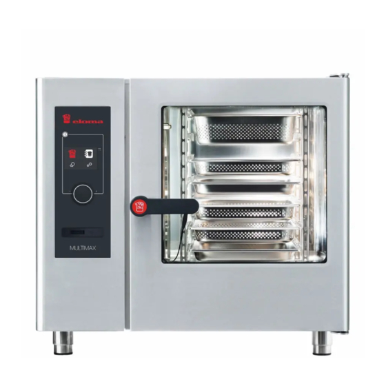
About this document Use of figures Figures are shown as examples and may differ from the scope of delivery of the combi steamer. Variants and device sizes The MULTIMAX combi steamer is supplied in the following sizes: Designation Version Variant 6-11 6 inserts GN 1/1 Table-top device... -
Page 11: Safety
Safety Safety All Eloma devices comply with the relevant safety standards. However, this does not mean that all residual risks, such as those caused by incorrect operation, can be ruled out. Qualifications of operating staff Operating staff must be familiar with and adhere to the respective valid regional regulations when operating the combi steamer. -
Page 12: Safety Notes
– Close the operating company's water tap. Make sure that repairs are only carried out by an authorised Eloma service partner and/or qualified specialists. WARNING! Risk of injury from parts falling out ... - Page 13 Safety DANGER! Perception of leaking gas and detection of the formation of smoke and fires If you smell gas: – Stop the operating company's gas and energy supply – Immediately ventilate the set-up location and exit it promptly – Do not actuate any switches or small electrical devices –...
- Page 14 Safety WARNING! Risk of burns from hot surfaces Wear protective clothing (e.g. long-sleeved clothing and protective gloves). Apply the brake on the tray trolley/mobile plate rack. Do not touch the rack or tray trolley/mobile plate rack when removing the cooked product.
- Page 15 Safety CAUTION! Risk of fire due to combustible materials, soiling and grease films Do not load combi steamers with food products which contain highly flammable substances (e.g. food products with alcohol). Make sure that there are no flammable materials above the combi steamer.
- Page 16 Safety CAUTION! Damaged glass panes Do not operate the device with damaged glass panes and faulty cooking chamber light. Dispose of any foods which are contaminated with glass fragments. CAUTION! Material damage due to overheating Make sure that the supply air opening and ventilation slats are unobstructed and not covered.
- Page 17 Safety 2.2.3 During cleaning WARNING! Risk of burns from hot surfaces Allow the combi steamer to cool down slowly before cleaning. WARNING! Risk of chemical burns from cleaners and rinsing agents Adhere to the safety notes for the stipulated cleaner and rinsing agent (see section 6.1) When changing the canisters for cleaner or rinsing agent: ...
- Page 18 WARNING! Risk of fire due to improper maintenance Make sure that maintenance work is only carried out by an authorised Eloma service partner. Adhere to the maintenance intervals (see section 6.8). Adhere to the rules of conduct in case of fire (see section 2.2.1).
-
Page 19: Description Of The Device - Functional Parts, Operation And Displays
Characteristics of the Eloma MULTIMAX combi steamer The MULTIMAX is the reliable workmate. The multifunctional Eloma combi steamer provides the kitchen team with support for all working procedures and thus makes sure that the chef can do his job with the requisite passion and concentration. -
Page 20: Functional Parts
Description of the device - functional parts, operation and displays Functional parts 3.2.1 Device overview, table-top devices Fig. 1: Main components of a table-top device, electric, right-hinged door Door handle Inner door Cooking chamber door Drip tray Cooking chamber USB connection port, locking panel Ventilation slats Hose with spray head Operating panel with touch display, push/twist knob, On/Off key... - Page 21 Description of the device - functional parts, operation and displays 3.2.2 Device overview, standalone devices Fig. 2: Main components of the standalone device, gas, right-hinged door Door handle Inner door Cooking chamber door Drip tray Cooking chamber USB connection port with locking panel Ventilation slats Hose with spray head Operating panel with touch display, push/twist knob, On/Off key...
-
Page 22: Operating Modes
Description of the device - functional parts, operation and displays Operating modes 3.3.1 Steam The foods are cooked at a constant temperature, surrounded by a high level of moisture (water vapour). Blanching, poaching and boiling are also covered by the steaming operating mode. 3.3.2 Combi-cooking Combi-cooking uses a combination of moisture and temperature to create... - Page 23 Description of the device - functional parts, operation and displays On combi steamers with the optional autoclean function: If the additional preheat/cool down function is activated and the temperature is < 100 °C/< 212 °F, water is sprayed into the cooking chamber through the autoclean lance to cool down the cooking chamber.
-
Page 24: Special Programs
Description of the device - functional parts, operation and displays Special programs Special programs are cooking programs which are preconfigured with recommended settings, which can however be changed. 3.5.1 Delta-T cooking The special Delta-T cooking program is a special form of low-temperature cooking. -
Page 25: Edit The Basic Setting
The stick must be of protection class IPX-5. 3.7.1 Device to USB transfer The following data can be copied from the combi steamer to the USB stick. This data can also be analysed, edited and printed using Eloma's Eloma-ProConnect software. Cooking programs ... - Page 26 Description of the device - functional parts, operation and displays 3.8.2 Change the basic setting To change the basic settings, the following access data is required: Password: 1234 The following parameters can be changed: Time display format: – 24 hour clock –...
-
Page 27: Control System Structure And Operation
ON/OFF key 5.7-inch touchscreen Push/twist knob Socket for external core temperature probe (optional) USB connection port with locking panel (MULTIMAX 6-11 and 10-11 only, on MULTIMAX 20-11 and 20-21 USB port as on GeniusMT) Fig. 3: Operating controls ON/OFF key... -
Page 28: Operating The Controller
Control system structure and operation USB port Data exchange can be performed via the USB port (see section 3.7 for more details). Operating the controller 4.2.1 Start settings Standby display The combi steamer is ready for operation. Fig. 4: Standby display Start display Selecting the main function fields:... - Page 29 Control system structure and operation Symbol Function Start display Manual cooking Program list Cleaning Settings/Service Tab. 5: Function fields in the start display Information: The functions in the start display can only be activated by touching the icons on the display screen. 4.2.2 Manual cooking Manual cooking...
- Page 30 Control system structure and operation Symbol Function Steam Combi-cooking Convection Preheat Start Cancel/stop Current time Back to previous display or start display Save Add cooking program steps Additional functions Tab. 6: Operating interface for manual cooking...
- Page 31 Control system structure and operation The cooking modes steaming, combi-cooking and convection can be selected by touching the corresponding icons. The selected cooking mode is shown in bright green with a grey background. The default values are displayed for the selected cooking mode. There are further navigation and main menu functions at the top/right edge of the screen.
-
Page 32: Cooking Settings For Combi-Cooking, Steaming And Convection
Control system structure and operation Cooking settings for combi-cooking, steaming and convection 4.3.1 Basic settings for manual cooking Fig. 7: Basic settings for combi-cooking Item Function Default value Setting range 30 °C … 300 °C Temperature 150 °C 10% … 30% (in 5% increments) Humidification 30% …... - Page 33 Control system structure and operation Changing the settings Information: The settings for temperature, moisture and the cooking duration are changed in the same way for steam cooking and convection cooking. Therefore, only the settings for combi-cooking are shown in detail. Parameter Description Temperature setting...
- Page 34 Control system structure and operation Parameter Description Cooking time/core temperature setting – Cooking time (basic setting) When the time is set, the colour of the symbol and the value switches from white to bright green on a grey background. 00:00 h to 23:59 h by turning the push/twist knob to the left/right Setting range: Continuous operation is possible (turn to...
- Page 35 Control system structure and operation 4.3.2 Basic settings for steam cooking Fig. 8: Basic settings for steam cooking Item Function Default value Setting range 30 °C … 130 °C Temperature 99 °C Steam 100% Constant, cannot be changed 00:01 h … 23:59 h Cooking time 00:30 h 20 °C …...
- Page 36 Control system structure and operation 4.3.3 Basic settings for convection mode Fig. 9: Basic settings for convection mode Item Function Default value Setting range 30 °C … 130 °C Temperature 180 °C Clima Aktiv (active dehumidification) closed Clima Aktiv (active dehumidification) open 00:01 h …...
- Page 37 Control system structure and operation Open/close Clima Aktiv (active dehumidification) selection: The selected function (2) is shown as a larger icon whilst the inactive function (3) can be seen in reduced size at the top left. The function does not start until the icon of the selected function is touched and the colour switches from white to bright green.
- Page 38 In the process, the number of green bars indicates the current speed level of the fan. You push the push/twist knob to confirm the setting you have made. Information: This function can only be activated on table-top devices Multimax 6-11 and 10-11.
- Page 39 Control system structure and operation Fig. 12: Fan timing function menu You select the bottom icon to access a non-adjustable timer function for the fan. The speed cannot be changed. The fan speed level selection menu is deactivated. Preconfiguring the start time Fig.
-
Page 40: Generating, Selecting And Editing Program Steps
Control system structure and operation The start time can be preconfigured to a time from 00:00 h to 23:59 h. If the setting is changed, it is also possible to enter the hours from 0 to 12 am/pm. The desired time is set by turning the push/twist knob and confirmed by pushing it. - Page 41 Control system structure and operation The number of the current program step and the total quantity of program steps can be seen on the operating panel (e.g. Further program steps are generated by activating the "plus" symbol and the following display for selecting the start of manual cooking 4.4.2 Viewing and changing program steps If the program step field in the border menu...
- Page 42 Control system structure and operation 4.4.3 Deleting program steps Fig. 16: Deleting a program step Deleting a program step. The last program step of the current cooking program is removed by touching the delete symbol (in this case, step 2). The current quantity of program steps is displayed (in this case, 2/2)
- Page 43 Control system structure and operation 4.4.4 Saving programs Fig. 16: Saving programs display Saving programs: The white save icon in the left-hand border menu is activated by selecting it. It then appears in bright green and the display switches immediately to the saving display 4.4.5 Dialogue display for saving a (new) cooking program Fig.
- Page 44 Control system structure and operation The next available program number is displayed. A maximum of 99 programs are possible Save the program with the new number Preconfigured numbers cannot be changed 4.4.6 Dialogue display for saving a duplicated or modified cooking program Fig.
- Page 45 Control system structure and operation Fig. 19: No free program number If there are no more free program numbers, the "Save As..." icon is deactivated and "FULL" is displayed The user can overwrite the current program number (e.g. 15) if he wishes to continue saving (fig.
-
Page 46: Working With The Program List
Control system structure and operation Working with the program list 4.5.1 Selecting from the program list You touch the icon in the start display to access the following cooking program list: Fig. 20: Cooking program list display You scroll through the list (from 1 to max. 99) by turning the push/twist knob and select the desired program by pushing the push/twist knob ... - Page 47 Control system structure and operation Fig. 21: Display of cooking program information To close the information display, you select the symbol. The start display with the parameters is then displayed. Fig. 22: Start display for the selected cooking program The respective program step and the total quantity of cooking steps are displayed.
- Page 48 Control system structure and operation 4.5.2 Selecting special programs You touch the symbol to access the selection of the special programs for low-temperature cooking, Delta-T cooking and regeneration. Fig. 23: Selection display for special programs Item Function Low-temperature (LT) cooking Delta-T cooking Regeneration Special programs active...
- Page 49 Control system structure and operation Low-temperature (LT) cooking Fig. 24: LT cooking selection for steaming, combi-cooking and convection Delta-T cooking Fig. 25: Delta-T cooking selection...
- Page 50 Control system structure and operation 2 versions of Delta-T cooking can be used: – Presets for steaming and convection accordingly – Settings for combi-cooking Function Default value Setting range 30 °C … 300 °C Temperature 75 °C 20 … 100% Humidification ...
- Page 51 Control system structure and operation Fig. 27: Display of the setting for regeneration...
-
Page 52: Single-Step And Multiple-Step Manual Cooking Programs
Control system structure and operation Item Function Default value Setting range Temperature 130 °C 30 °C ... 300 °C 10% … 100% Humidification 00:01 h … 23:59 h Time 00:08 h 20 °C … 100 °C Core 70 °C temperature Preheat Constant, cannot be changed Tab. - Page 53 Control system structure and operation 4.6.2 Multiple-step manual cooking program Further program steps can be entered whilst a cooking program is in progress. Fig. 29: Sequence of a manual program with multiple steps Fig. 30: Sequence of a program from the program list Further program steps can be entered whilst a cooking program is in progress.
- Page 54 Control system structure and operation 4.6.3 Sequence of the special regeneration program Fig. 31: Regeneration sequence Only the symbol appears, and no description.
-
Page 55: Cleaning And Servicing Control
Control system structure and operation Cleaning and servicing control 4.7.1 Semi-automatic cleaning You touch the symbol in the start display to access the cleaning program start. Fig. 32: Manual cleaning start screen 1. Select <Start> 2. <Cool down> starts when the temperature is too high Fig. - Page 56 Control system structure and operation 5. Once the door has been closed, the application time starts automatically, and a steaming phase follows until the symbol flashes again and the signal tone sounds. 6. Once the door has been opened, the symbol flashes, indicating thorough rinsing with the hand-held spray head.
-
Page 57: Service And Settings
Control system structure and operation Fig. 35: Display of the progress of the selected autoclean level ® 3. The autoclean program is started by touching the "start" symbol and the remaining time until the end of cleaning is displayed The program can be stopped/cancelled by selecting the "stop"... - Page 58 Control system structure and operation Fig. 36: Display and activation of service/settings 1. You turn the push/twist knob to scroll through the list of setting information (day, time, language etc.) and you call up the service/settings field by pressing the push/twist knob. –...
- Page 59 Control system structure and operation Fig. 37: Password entry 2. The number combination for the respective access level has to be entered using the lower numerical keypad and confirmed by selecting the arrow at the right-hand edge. To correct the input, use the symbol.
- Page 60 Control system structure and operation Fig. 38: Screen for editing cooking programs 4. You turn the push/twist knob to scroll through the program list and you activate or deactivate the desired cooking program by pressing the push/twist knob. The boxes for activated programs are checked. –...
-
Page 61: Readiness For Operation
Readiness for operation Readiness for operation Opening and closing the cooking chamber door NOTICE! Before starting work it is imperative that you familiarise yourself with section 2 "Safety"! Pay attention to whether the door is right-hinged or left-hinged! ... -
Page 62: Loading And Emptying The Device
Readiness for operation Loading and emptying the device Information: Before starting work, it is imperative that you familiarise yourself with section 2 "Safety" and the special notes and warnings (see section 5.5.3, p. 68) Only use the stipulated container sizes ... - Page 63 Readiness for operation 1. Open the cooking chamber door 2. Insert the loading trolley 3. Secure the loading trolley with brake lever 4. Close the cooking chamber door and start the cooking process 5. Open the cooking chamber door 6. Release the brake lever 7.
-
Page 64: Switching The Combi Steamer On And Off
Readiness for operation 1. Open the cooking chamber door 2. Insert the loading trolley as far as it will go by the bow handle (1) 3. Secure the loading trolley with castors with brakes 4. Remove the bow handle 5. Close the cooking chamber door and start the cooking process 6. -
Page 65: Measures In Case Of A Power Interruption Or Power Failure
Readiness for operation 5.3.2 Switching off the device for short breaks in operation 1. Press the On/Off key 2. The display is extinguished 3. Opening/closing the cooking chamber door to the pre-latched position 5.3.3 Switching off the device for longer breaks in operation 1. -
Page 66: Use Of Other Device Components
Readiness for operation Use of other device components 5.5.1 Hose with spray head WARNING! Generation of hot steam when spraying water into the hot cooking chamber! Scalding Before cleaning the cooking chamber with the hose with spray head, allow the cooking chamber to cool down. The hose with spray head must only be used to clean the cooking chamber and not for cooling! 1. - Page 67 Readiness for operation 5.5.2 Core temperature probe (optional) Two probe variants are available: External core temperature probe Fig. 41: External connection socket for core temperature probe Fig. 42: External core temperature probe with connection...
- Page 68 Readiness for operation CAUTION! Risk of burns from hot temperature probe! Minor skin burns Wear protective gloves. CAUTION! Risk of injury from the tip of the temperature probe! Puncture wound Take care not to injure yourself or other persons in the direct vicinity.
- Page 69 Readiness for operation Maximum load for the tray trolleys/mobile plate racks and racks Size Maximum load 6-11 30 kg (max. 15 kg per insert) 10-11 50 kg (max. 15 kg per insert) 20-11 150 kg (max. 15 kg per insert) 12-21 150 kg (max.
- Page 70 Readiness for operation Fig. 43: Fitting the handle on the tray trolley 1. Push the handle through the lug from below. 2. Push the handle down. Information: Transport the tray trolley for table-top devices with a transportation trolley! Only use a transportation trolley if the table-top device is placed on a subframe, base cabinet or heated base cabinet of the same height.
-
Page 71: Cleaning, Servicing And Maintenance
Stipulated cleaners and rinsing agents The following cleaners and rinsing agents are approved for cleaning the cooking chamber: Eloma Multi-Clean special cleaner Eloma Multi-Clean rinsing agent Information: The warranty will be rendered null and void with immediate effect if the stipulated cleaners are not used. -
Page 72: Notes On Manual Cleaning
Cleaning, servicing and maintenance Notes on manual cleaning CAUTION! Risk of burns from hot surfaces! Skin burns Allow the combi steamer to cool down before cleaning. CAUTION! Risk of scalding from hot steam! Skin burns Allow the combi steamer to cool down before cleaning. 6.2.1 Recommended cleaning intervals Interval... - Page 73 Cleaning, servicing and maintenance Interval What as necessary Twist knob Manually in the wash basin or in the dishwasher Tab. 16: Description of cleaning intervals 6.2.2 Cleaning the cooking chamber with pressure pump sprayer Information: ® On combi steamers with an autoclean cleaning program: ®...
-
Page 74: Cleaning The Cooking Chamber With The Autoclean Cleaning Program (Optional)
Cleaning, servicing and maintenance Cleaning the cooking chamber with the autoclean cleaning program (optional) 6.3.1 Cleaning and servicing programs Cleaning program Application First level/level 01 Light to medium soiling from preparation of steamed vegetables, meat products or fish and 00:45 h occasional preparation of fried or grilled products. - Page 75 Cleaning, servicing and maintenance 6.3.2 Starting the autoclean cleaning program Requirement The cooked product has been removed. Accessories (e.g. containers) have been removed. The grease filter has been removed. For standalone devices: The tray trolley is in the cooking chamber. ...
-
Page 76: Cleaning The Drip Tray On The Cooking Chamber Door
Cleaning, servicing and maintenance Information: The connections for the cleaner and rinsing agent are marked on the combi steamer. Working steps 1. Switch off the combi steamer. 2. Disconnect the hoses for cleaner and/or rinsing agent from the canisters. 3. Position the new canisters underneath the combi steamer. 4. -
Page 77: Cleaning The Door Seal
Cleaning, servicing and maintenance Working steps 1. Push the fastening clip below the drip tray down. 2. Pull the drip tray out of the mount towards the front. 3. Clean the drip tray. 4. Push the drip tray into the mount. 5. -
Page 78: Replacing The Water Softener
Cleaning, servicing and maintenance NOTICE! Damage as a result of opening the inner door incorrectly! Damage to the door mount Do not open the inner door more than 90°. Keep hold of the inner door while cleaning. Check the door mount regularly. -
Page 79: Maintenance Intervals
Maintenance intervals WARNING! Risk of fire due to improper maintenance! Burns Make sure that maintenance work is only carried out by an Eloma service partner. Adhere to the stipulated maintenance intervals. Have maintenance carried out at least once a year by an Eloma service partner. -
Page 80: Clearing Faults And Malfunctions
Clearing faults and malfunctions Clearing faults and malfunctions NOTICE! If the signal light or an audible signal tone indicates a fault, the device is faulty. The device will need to be switched off and/or disconnected from the mains, and a service technician will need to be informed for troubleshooting purposes. -
Page 81: Fault Messages And Remedies
The rinsing agent is empty. (30%) Replace the water The water softener is softener. empty. Contact an Eloma service The water pressure is too partner. low. Close the cooking The cooking chamber chamber door. door is open. - Page 82 Clearing faults and malfunctions Code Display Possible cause Troubleshooting Contact an Eloma service partner. Contact an Eloma service Cooking chamber probe partner. 1 is faulty. Contact an Eloma service Cooking chamber probe partner. 2 is faulty. ...
- Page 83 Clearing faults and malfunctions Code Display Possible cause Troubleshooting Contact an Eloma service Insufficient water partner. available for steaming The combi steamer can only operating mode. be operated with restrictions. Contact an Eloma service 511-513 Overheating of electrical partner.
- Page 84 Troubleshooting Select the symbol with the Re-start gas system 2. small flame. If the fault message occurs repeatedly: Contact an Eloma service partner. Tab. 19: Description of fault messages, possible causes and measures for gas and electrical devices...
-
Page 85: Disposal And Environmental Protection
Disposal and environmental protection Disposal and environmental protection Strict adherence to the legal rules, quality standards and regulations, and a high environmental awareness form the basic standards for development, production and servicing of the combi steamers on our premises. However, as well as valuable recyclable materials, these devices with electronic circuits also contain harmful substances which were necessary for their... -
Page 86: Appendix
Appendix Appendix Check list, training/start of operation Inspection criterion Inspection note General Training on construction and function provided? Section on safety read and noted? Trained on operation of the main elements? Training and functional check before start of operation Lighting functional? Screen display functional? Hose with spray head functional? ®... - Page 87 – Upload/download programs, images, acoustic signals – Additional programs (Delta-T, LT cooking, regeneration) Eloma customer service information Eloma forum dates Warranty extension to 2 years on registration User and service hotline Info 24 ProConnect Tab. 20: Check list, initial training on start of operation...
-
Page 88: Declaration Of Conformity, Certificates Etc
Appendix Declaration of conformity, certificates etc. - Page 89 Appendix...
- Page 90 Appendix...
- Page 91 Appendix Maintenance comments, notes etc.
- Page 92 Eloma GmbH . Innovative Koch- & Backtechnik...
Need help?
Do you have a question about the MULTIMAX 6-11 and is the answer not in the manual?
Questions and answers