
Related Manuals for IMS IB462H


Summary of Contents for IMS IB462H
- Page 1 sales@artisantg.com artisantg.com (217) 352-9330 | Visit our website - Click HERE...
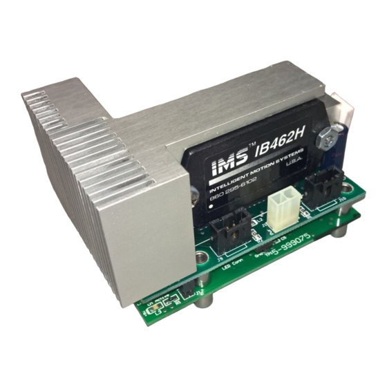
- Page 2 , in c . Excellence in M otion IB462H HIGH PERFORMANCE MICROSTEPPING DRIVE FEATURING THE INT-462H INTERFACE BOARD AND THE OSC-462H VARIABLE SPEED CONTROL O P E R A T I N G I N S T R U C T I O N S 370 N.
- Page 3 Intelligent Motion Systems, Inc. products in life support or aircraft applications assumes all risks of such use and indemnifies Intelligent Motion Systems, Inc., against all damages. IB462H Half/Full Step Driver Hybrid Operating Instructions Revision 12.19.2002 ©2002 by Intelligent Motion Systems, Inc.
-
Page 4: Table Of Contents
Pin Assignment and Description .................. 10 Section 1.3: Mounting the IB462H ............11 Section Overview ......................11 Direct Mounting the IB462H to a PC Board ..............11 Mounting the IB462H using a Receptacle ..............12 Section 1.4: Theory of Operation ............13 Section Overview ...................... - Page 5 Figure 1.3.2 Direct PCB Mounting ................. 12 Figure 1.3.3 PCB Mounting using a Receptacle ............ 12 Figure 1.4.1 IB462H Block Diagram ..............13 Figure 1.4.2 Normal Mode Phase Sequence ............14 Figure 1.4.3 Wave Mode Phase Sequence ............15 Figure 1.4.4 Half Step Mode Phase Sequence .............
- Page 6 OSC-462H Connector P1 Pin Configuration ........53 Figure 2.2.3 OSC-462H Connector P3 Pin Configuration ........54 Figure 2.2.4 Inserting the IB462H into the OSC-462H .......... 55 Figure 2.2.5 Mounting the IB462H/OSC-462H Assembly ........55 Figure 2.2.6 Connecting the SPI Interface ............56 Figure 2.2.7...
- Page 7 Page Intentionally Left Blank...
- Page 8 Part I I B 4 6 2 H S e c t i o n 1 . 1 –I n t r o d u c t i o n S e c t i o n 1 . 2 –H a r d w a r e S p e c i f i c a t i o n s S e c t i o n 1 .
-
Page 9: Features And Benefits
T h e I B 4 6 2 H The IB462H is a low cost, high performance alternative to larger drives. The small size of the IB462H makes it ideal for system designs where space is at a premium without having to sacrifice performance as a result. -
Page 10: Section 1.1: The Ib462H
Ensure that the Power Supply output voltage does not WARNING! exceed the maximum input voltage of the IB462H/INT-462! The IB462H rear plate MUST be kept to 70° or below WARNING! or damage may occur to the device! Use of an external heat sink and the included thermal pad is required to maintain a rear plate temperature of 70°C or below! -
Page 11: Section 1.2: Hardware Specifications
S e c t i o n O v e r v i e w This section will acquaint you with the dimensional information, pin descrip- tion, power, environmental and thermal requirements of the IB462H. It is broken down as follows:... -
Page 12: Electrical Specifications
° ° Table 1.2.2: IB462H Thermal Specifications WARNING! The IB462H rear plate MUST be kept to 70° or below or damage may occur to the device! USe of an external heat sink and the included thermal pad is required to maintain a rear plate temperature of 70°C or below! -
Page 13: Pin Assignment And Description
. s t . t u & & & . t u & & & . t u Table 1.2.3: IB462H Pin Assignment and Description NOTE: Dot on lower left of label indicates the location of pin 1. -
Page 14: Section 1.3: Mounting The Ib462H
D i r e c t M o u n t i n g t h e I B 4 6 2 H t o a P C B o a r d The IB462H is designed to be soldered directly into a PC board. The follow- ing diagram contains the hole pattern and recommended pad sizes for direct mounting of the IM483H/IM805H. -
Page 15: Mounting The Ib462H Using A Receptacle
M o u n t i n g t h e I B 4 6 2 H u s i n g a R e c e p t a c l e If desired, a receptacle may be used to connect the IB462H to the user’s PCB. -
Page 16: Section 1.4: Theory Of Operation
C i r c u i t O p e r a t i o n The IB462H is a bipolar chopping stepper motor drive. It receives step clock, direction and mode signals from the system controller to generate constant phase currents which are adjustable in magnitude. -
Page 17: Output Wave Sequences
In wave drive mode one phase is energized at a time. This mode is enabled by selecting full step mode when the IB462H is in an even numbered state. To select this mode, power the IB462H, send a single step clock pulse then sink... -
Page 18: Timing
STEP CLOCK PHASE A PHASE A PHASE B PHASE B Figure 1.4.3: Wave Mode Phase Sequence H a l f S t e p M o d e In half step mode the phasing alternates from one phase energized to two phases energized. -
Page 19: Section 1.5: Power Supply Requirements
T h e P o w e r S u p p l y - D r i v e r R e l a t i o n s h i p The IB462H is very current efficient as far as the power supply is concerned. - Page 20 The current regeneration may be too large for the regulated supply to absorb. This could lead to an over voltage condition which could damage the output circuitry of the IB462H. Non IMS switching power supplies and regulated linear supplies with overcurrent protection are not recommended because of their inability to handle the surge currents inherit in stepping motor systems.
-
Page 21: Selecting A +5Vdc Supply
S e l e c t i n g a + 5 V D C S u p p l y In the event that you are manufacturing your own interface for the IB462H you will need to supply +5VDC to power the logic circuitry inside the hybrid. -
Page 22: Ac Line Filtering
Since the output voltage of an unregulated power supply will vary with the AC input applied it is recommended that an AC line filter be used to prevent damage to the IB462H due to a lightning strike or power surge. WARNING! Verify that the power supply wiring is correct prior to power application. -
Page 23: Section 1.6: Motor Requirements
Polyphase Synchronous Motor. This means it has multiple phases wound in the stator and the rotor is dragged along in synchronism with the rotating magnetic field. The IB462H is designed to work with the following types of stepping motors:... -
Page 24: Figure 1.6.1 Per Phase Winding Inductance
W i n d i n g I n d u c t a n c e Since the IB462H is a constant current source, it is not necessary to use a motor that is rated at the same voltage as the supply voltage. What is impor- tant is that the IB462H is set to the motor’s rated current. - Page 25 IMS stocks the following 1.8° hybrid stepping motors that are recommended for the IB462H. All IMS motors are CE marked. For more detailed informa- tion on these motors please see the IMS Full Line Catalog or the IMS web site at www.imshome.com.
-
Page 26: Motor Wiring
M2-2232-S ..............M2-2232-D M2-2240-S ..............M2-2240-D IMS also carries a new series of 23 frame enhanced stepping motors that are recommended for use with the IB462H. These motors use a unique relationship between the rotor and stator to generate more torque per frame size while ensuring more precise positioning and increased accuracy. -
Page 27: Connecting The Motor
NOTE: The physical direction of the motor with respect to the direction input will depend upon the connection of the motor windings. To switch the direction of the motor with respect to the direction input, switch the wires on either phase A or phase B outputs. -
Page 28: Figure 1.6.3 8 Lead Parallel Motor Configuration
P a r a l l e l C o n n e c t i o n An 8 lead motor in a parallel configuration offers a more stable but lower torque at lower speeds, but because of the lower inductance there will be higher torque at higher speeds. -
Page 29: Figure 1.6.5 6 Lead Full Coil Motor Configuration
F u l l C o i l C o n f i g u r a t i o n The full coil configuration on a six lead motor should be used in applications where higher torque at lower speeds is desired. This configuration is also referred to as full copper. -
Page 30: Section 1.7: Interfacing To The Ib462H
I n t e r f a c i n g t o t h e I B 4 6 2 H S e c t i o n O v e r v i e w The IB462H was designed to be incorporated directly in the user’s printed circuit board. In order to operate, the IB462H must have the following connections: Layout and interface guidelines. -
Page 31: Motor Power
Pins 13, 14 (+V), and 15, 16 (Ground) are used to connect motor DC power to the IB462H. Two local capacitors are needed, connected between pins 13, 14 and 15, 16. These must be located as close to the IB462H’s motor power input pins as possible to ensure stable operation. -
Page 32: Vdc Input
R e q u i r e d C a p a c i t o r A 22 microfarad 10V tantalum capacitor must be placed as close to the IB462H as possible between the +5VDC input pin 5 and ground (See figure 1.7.1 for PCB layout example). -
Page 33: Figure 1.7.2 Current Adjust/Reduction Circuit
Range 0A to 2A per Hold Phase. NOTE! These equations ONLY apply to the circuit example below. If using the IB462H with an INT-462 see Section 2.1: The INT-462, for details on adjust and reduction resistor values. 74HC123 221k... -
Page 34: Interfacing The Logic Inputs
I n t e r f a c i n g t h e L o g i c I n p u t s The inputs to the IB462H are internally pulled up to the +5VDC supply. Figure 1.7.3 shows the inputs and their associated pull up resistor values. See Section 1.2: Hardware Specifications, for input tolerance. -
Page 35: Minimum Required Connections
M i n i m u m R e q u i r e d C o n n e c t i o n s The following diagram illustrates the minimum connections required to operate the IB462H. 150µF for each Amp Peak... -
Page 36: Section 1.8: Troubleshooting
B a s i c Tr o u b l e s h o o t i n g In the event that your IB462H doesn’t operate properly the first step is to identify whether the problem is electrical or mechanical in nature. The next step is to isolate the system component that is causing the problem. - Page 37 S y m p t o m Motor moves in the wrong direction. P o s s i b l e P r o b l e m Motor phases may be connected in reverse. S y m p t o m Fault LED on Interface Board is illuminated.
-
Page 38: Contacting Application Support
C o n t a c t i n g A p p l i c a t i o n S u p p o r t In the event that you are unable to isolate the problem with your IB462H the... -
Page 39: The Ims Web Site
R e t u r n i n g Yo u r P r o d u c t t o I M S If Application Support determines that your IB462H needs to be returned the factory for repair or replacement you will need to take the following steps: Obtain an RMA (Returned Material Authorization) number and shipping instructions from Customer Service. - Page 40 Part II O p t i o n s A n d A c c e s s o r i e s S e c t i o n 2 . 1 – I N T- 4 6 2 S e c t i o n 2 .
- Page 41 Page Intentionally Left Blank...
-
Page 42: Section 2.1: The Int-462 Interface Board
S e c t i o n 2 . 1 T h e I N T- 4 6 2 I n t e r f a c e B o a r d I N T- 4 6 2 F e a t u r e s This section covers the INT-462 interface board for the IB-462H. -
Page 43: Pin Assignment And Description
P i n A s s i g n m e n t a n d D e s c r i p t i o n . t u y l l . t u c i t y l l c i t y l l i t c... -
Page 44: Thermal Specifications
Table 2.1.2: INT-462 Electrical Specifications T h e r m a l S p e c i f i c a t i o n s The following thermal information is repeated from Section 1.2 of the IB462H portion of this document. -
Page 45: Mounting The Int-462
M o u n t i n g t h e I N T- 4 6 2 WARNING! The IB462H Driver must be mounted to a Heat Sink at all power levels. The Isolated Thermal Pad supplied with the H-462H Heat Sink must aslo be used. -
Page 46: Table 2.1.4 Current Adjust Resistor Values
The INT-462 uses a 1mA current source to provide a reference level to the current adjust pin (Pin 1) of the IB462H driver. To control the output curent a resistor is placed between Pins 13 and 14 of the interface board. Connection of this resistor is essential for the IB462H/INT-462 to operate. -
Page 47: Table 2.1.5 Jumper Jp3 Shunt Placement Options
R e d u c i n g t h e O u t p u t C u r r e n t The INT-462 will automatically reduce the current in the motor windings .5 seconds after the falling edge of the last step clock pulse. There are two possible ways that this may be done. -
Page 48: Figure 2.1.3 Current And Reduction Adjustment Resistor Connection
D i s a b l i n g t h e D r i v e r O u t p u t s ( E N O N M o d e ) The second method is to disable the driver outputs. In this configuration the driver outputs will disable 0.5 seconds after the following edge of the last step clock pulse. -
Page 49: Figure 2.1.4 Optically Isolated Input Circuitry
INT-462 allows for easy “plug and play” interfacing with an array of controllers ranging from the IMS LYNX to a variety of PLCs. These inputs may be powered using one of two methods: An external +5 to +24 VDC power supply or by using the on-board +5 volts. -
Page 50: Figure 2.1.5 Powering The Opto-Couplers Using The On-Board +5 Vdc
If the controller or PLC being used with the INT-462/IB462H has a voltage output, this may also be used to power the opto-couplers. If this mode of powering the logic inputs is used, the shunt on JP2 must be placed between pins 1 and 2 (factory default placement). -
Page 51: Figure 2.1.6 Jumper Jp1 Showing Full Step Mode Selected
F a u l t P r o t e c t i o n C i r c u i t r y / F a u l t O u t p u t The INT-462H adds phase to ground fault protection to the IB462H. If a phase to ground fault is detected, the driver will set the fault output and the red LED will illuminate. -
Page 52: Figure 2.1.7 Minimum Required Connections
Pin 11 of the terminal strip. M i n i m u m R e q u i r e d C o n n e c t i o n s Figure 2.1.7 illustrates the connections required to operate the INT-462/IB462H Interface board/driver combination. -
Page 53: Section 2.2: The Osc-462H Variable Speed Control
S e c t i o n O v e r v i e w The purpose of this appendix is to aquaint the user with the OSC-462H variable speed control optional add-on for the IB462H driver hybrid. Covered are: OSC-462H Features... -
Page 54: Osc-462H Specifications
The velocity will vary between a user configured initial velocity and a maximum velocity with voltage level applied to the input. Axis direction is controlled by the direction input. In addition to this powerful array of features, the OSC-462H has buffered step clock and direction outputs to facilitate cascading of drives. -
Page 55: Table 2.2.1 Osc-462H Thermal Specifications
T h e r m a l S p e c i f i c a t i o n s ) ° ° ° ° Table 2.2.1: OSC-462H Thermal Specifications E l e c t r i c a l S p e c i f i c a t i o n s a t l t u l s t i... -
Page 56: Figure 2.2.2 Osc-462H Connector P1 Pin Configuration
P i n A s s i g n m e n t a n d D e s c r i p t i o n Phase A - Pin 1 Phase A - Pin 2 +V (+12 to +40VDC) - Pin 3 Power Ground - Pin 4 Phase B - Pin 5 Phase B - Pin 6... -
Page 57: Mounting The Osc-462H
M o u n t i n g t h e O S C - 4 6 2 H The OSC-462H/IB462H must be mounted to a heat sink in order to maintain a rear plate temperature of less than 70°C on the IB462H driver. -
Page 58: Figure 2.2.4 Inserting The Ib462H Into The Osc-462H
L-gracket is also available as an option. OSC-462H IB462H IB462H Rear Plate (Heat Sink Side) Figure 2.2.4: Inserting the IB462H into the OSC-462H #6 Stainless Machine Screw #6 Stainless Lock Washer OSC-462H #6 Stainless Flat Washer TI-462H Thermal Pad... -
Page 59: Osc-462H Wiring And Connections
M o t o r P o w e r / G r o u n d ( + V - P i n 3 , G N D - P i n 4 ) Motor power for the OSC-462H/IB462H assembly will have the same recommended specifications as found in Section 1.5: Power Supply... -
Page 60: Figure 2.2.7 Interfacing The Speed Control Input With A Potentiometer
S t e p p i n g M o t o r ( Ø A - P i n s 1 & 2 , Ø B - P i n s 5 & 6 ) Motor selection for the OSC-462H/IB462H will have the same recommended specifications as found in Section 1.6: Motor Requirements of this document. - Page 61 This input would be used if an external 0 - 40kHz clock input is being used as a motion clock for the IB462H. This input will increment the motor only if the /Start input is in a logic HIGH (internal oscillator stopped) state.
-
Page 62: Table 2.2.5 Osc-462H Required Connections
M i n i m u m R e q u i r e d C o n n e c t i o n s The following connections illustrated in Table 2.2.5 and Figure 2.2.8 are required to operate the OSC-462H/IB462H assembly. . t u Ω... -
Page 64: Configuring The Osc-462H
U s i n g t h e C o n f i g u r a t i o n U t i l i t y The IMS Analog Speed Control Configuration Utility is an easy to install and use software program. -
Page 65: Configuration Parameters Explained
A c c e l e r a t i o n ( A C C L ) The ACCL parameter sets the acceleration and deceleration in steps per second . If the IB462H is in half step mode (STEP=H) the acceleration/ deceleration will be in half steps per second . If in full step mode (STEP=F) - Page 66 voltage seen on the speed control input will accelerate from 0 to the maximum set velocity. See the setup procedure located in “Setting the Configuration Parameters”, the next sub-section of this document. NOTE: In order to acheive the maximum set velocity (VM) on both sides of the joystick center position, the “C”...
-
Page 67: Setting The Configuration Parameters
H a l f / F u l l S t e p M o d e ( S T E P ) The STEP parameter specifies the mode of operation for the IB462H, either half step or full step. -
Page 68: Figure 2.2.10 Osc-462H Configuration Utility Screen
When operating as a velocity device the OSC-462H will output step clock pulses to the IB462H driver. The initial and maximum frequency of these pulses, and the rate which they accelerate between these values is established by the following four parameters:... -
Page 69: Figure 2.2.11 Initialization Mode
Figure 2.2.11: Intitialization Mode S e t t i n g t h e O S C - 4 6 2 H a s a J o y s t i c k I n t e r f a c e When operating as a joystick interface it is necessary that the joystick be calibrated. -
Page 70: Application Example #1: Connection And External Step/Direction
This application example shows the OSC-462H/IB462H connected to an external step clock/direction source, in this case a LYNX Control Module. The IB462H’s motion can be controlled by the LYNX, or third party motion controller with TTL or sinking (NPN) outputs. The OSC-462H responds to step clock and direction inputs when the /Start input is left N/C. -
Page 71: Application Example #2: Connection Of Osc-462 To Additional Half/Full Step Driver
This application sample shows a secondary IB series drive, such as an IB463 or IB1010, cascaded off of the OSC-462H step clock and direction outputs. Connected in this fashion the secondary driver will “follow” the primary drive, the IB462H. +VDC Line... - Page 72 Intelligent Motion Systems, Inc., warrants its products against defects in materials and workmanship for a period of 24 months from receipt by the end-user. During the warranty period, IMS will either, at its option, repair or replace products which prove to be defective.
- Page 73 Oceanside, CA 9 2 0 5 4 Email: hruland@imshome.com Phone: 7 6 0 / 9 6 6 -3 1 6 2 Fax: 7 6 0 / 9 6 6 -3 1 6 5 E-mail: motors@imshome.com IB462H Operating Manual OM-IB462H V.12.19.2002...
Need help?
Do you have a question about the IB462H and is the answer not in the manual?
Questions and answers