Table of Contents
Advertisement
Quick Links
intelligent motion systems, INC.
MICROSTEPPING
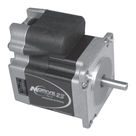
MDrive23Plus
Q U I C K R E F E R E N C E
370 N. MAIN ST., PO BOX 457, MARLBOROUGH, CT 06447
PH: (860) 295-6102, FAX: (860) 295-6107
Internet: www.imshome.com, E-Mail: info@imshome.com
Product Manuals
The MDrive23Plus Microstepping product manual contains full details about the
product. The manual is available on the CD which shipped with your product
and from the IMS web site at http://www.imshome.com.
Notes and Warnings
DO NOT EXCEED
+75 VDC
INCLUDES BACK EMF
Specifications
Electrical Specifications
Input Voltage (+V) Range*
Max Power Supply Current (Per MDrive23Plus)*
*Actual Power Supply Current will depend on Voltage and Load.
Environmental Specifications
Operating Temperature
Heat Sink
Motor
(non-condensing)
2
Sealing (Plus
-65 Only)
Isolated Input Specifications
Step Clock, Direction and Enable
Voltage Range (Sinking or Sourcing)
Current (+5V Max)
Current (+24V Max)
Motion Specifications
Digital Filter Range
Clock Types
Step Frequency (Max)
Step Frequency Minimum Pulse Width
Number of Microstep Resolution Settings
Available Microsteps Per Revolution
200
400
800
1000
12800
20000
25000
25600
1=0.01 deg/µstep
2=1 arc minute/µstep
Setup Parameters
Setup Parameters
Name
Function
MHC
Motor Hold Current
MRC
Motor Run Current
MSEL
Microstep Resolution
Motor Direction
DIR
Override
Hold Current Delay
HCDT
Time
CLK TYPE
Clock Type
CLK IOF
Clock Input Filter
Enable Active
EN ACT
High/Low
USER ID
User ID
M i n i m u m C o n n e c t i o n s
Sourcing Configuration
Controller
Logic Supply
+
I/O Power
MDrivePlus
Opto
GND
Step Out
Step
Dir. Out
Dir
+V
Pwr Gnd
+
Power Supply
Excellence in Motion
23
TM
MDrive23Plus-65
DO NOT
HOT PLUG
DC POWER, I/O OR
COMMUNICATIONS!
+12 to +75 VDC
-40°C to +85°C
-40°C to +100°C
IP-65 Compliant
50 nS to 12.9 µS (10 MHz to 38.8 kHz)
Step/Direction, Up/Down, Quadrature
1600
2000
3200
5000
6400
40000
50000
51200
36000
1
21600
3=0.001 mm/µstep
Range
Units
0 to 100
Percent
1 to 100
Percent
See Motion
µsteps/
Specifications
Full Step
0/1
—
0 or 2 - 65535
mSec
See Motion
—
Specifications
50 nS to 12.9 µS
(10 MHz to 38.8
nS (MHz)
kHz)
High/Low
—
3 Characters
Viewable
Viewable ASCII
ASCII
Sinking Configuration
Controller
Logic Supply
+
GND
Step Out
Dir. Out
+
Power Supply
Mechanical Specifications
Plus
2.02
(51.2)
1.63
(41.4)
Ø 0.25
(Ø 6.3)
2.22 SQ.
(56.4 SQ.)
Plus-65 (Sealed)
See Drawing Above
For Front Dimensions
E x t e r n a l E n c o d e r O p t i o n s
2 A
Differential
With cable: ED-CABLE-6
Pin 1
Pin 2
Orange/White: +5 VDC In
White/Orange: Ground
White/Blue: CH A -
+5 to +24 VDC
Blue/White: CH A +
8.7 mA
White/Green: CH B -
14.6 mA
Green/White: CH B +
White/Brown: Index -
Brown/White: Index +
Getting Started
5 MHz
Connecting Power and Control Inputs
100 nS
20
Using the minimum connections drawings, connect your DC Power Supply and, at the mini-
mum: Opto Reference (+5 to +24 VDC for sinking inputs, Controller Logic GND for sourc-
ing inputs), Step Clock and Direction. By default the MDrivePlus is in the enabled state.
10000
2
25400
3
Do not apply power to the MDrivePlus at this time.
Connecting SPI Communications
Install The Cable Drivers
This is a two part process, as two sets of drivers are installed: one for the cable, and one for a
Default
Virtual COM Port (VCP). The drivers will function with Windows XP SP2 or greater. Plug
5
the USB end of the communications cable (see drawings, opposite side) into your PC USB
25
Port.
256
1.
The Hardware Update Wizard will open, select "no, not at this time" and click next.
CW
2.
Select the option: Install from a specific location, click next.
3.
Browse to the folder on the CD: \Cable_Drivers\MD_CC30x_000\, click next.
500
4.
Click continue anyway on the Windows Logo Compatibility dialog.
Step/
Direction
5.
Click finish. The Hardware Update dialog will open again to install the VCP drivers.
200 nS
6.
Repeat steps 2 - 6 above to complete the installation.
(2.5MHz}
The COM Port the device is connected to will be listed in the Windows Device Manager,
which may be accessed by right-clicking the My Computer icon and selecting Properties.
High
Connect to the MDrivePlus
IMS
Plug the cable into the appropriate connector of the MDrivePlus, you may apply power at
this time.
Install SPI Motor Inter face
SPI Motor Interface is the configuration utility for the MDrivePlus Microstepping. This
simple GUI will set up and configure all of the setup parameters. SPI Motor Interface will
run on Windows XP SP 2 and greater.
MDrivePlus
1.
Insert the CD into the CD or DVD drive on your PC. The CD will autostart.
Opto
2.
Click the Software Button in the top-right navigation area.
3.
Click the SPI Motor Interface link.
Step
Dir
4.
Click SETUP in the Setup dialog box and follow the on-screen instructions.
A complete description of setup parameters with usage examples may be found in the
MDrivePlus Microstepping manual.
+V
Pwr Gnd
Visit the IMS web site for Interactive Tutorials on Cable Driver installation and SPI
Motor Interface installation and use! http://www.imshome.com/tutorials.html
1.90
(48.3)
Connector
Option
P1/P3
Ø 0.197
(Ø 5.0)
2.96
(75.2)
P2
1.856 SQ.
(47.1 SQ.)
L MAX1
L MAX2
Dimensions in inches (mm)
Motor Length LMAX1 (Single Shaft)
Single
2.65 (67.31)
Double
3.02 (76.71)
Triple
3.88 (98.55)
2.042
(51.9)
2.96
P2
(75.2)
P1
1.03 3
(26.2)
1.480
(37.6)
L MAX1
L MAX2
Dimensions in inches (mm)
Motor Length
LMAX1
Single
2.82 (71.63)
Double
3.16 (80.26)
Triple
4.02 (102.11)
Single-End
With cable: ES-CABLE-2
Pin 1
(Pin 1) Brown: Ground
Violet: Index
Blue: CH A
Orange: +5 VDC In
Yellow: CH B
MDrive23Plus Microstepping Quick Reference R111907
0.81
(20.6)
0.23
(5.8)
0.19
(4.9)
LMAX2 (Control Knob
or External Encoder)
3.36 (85.34)
3.73 (94.74)
4.59 (116.59)
0.81
(20.6)
0.230 ±0.004
(5.8 ±0.1)
LMAX2
3.48 (88.39)
3.82 (97.03)
4.67 (118.62)
Differential
Encoder
2.04
(51.8)
Single-End
Encoder
1.42
(36.1)
.
1.20
(30.4)
.
1.22
(31.0)
Advertisement
Table of Contents

Subscribe to Our Youtube Channel
Related Manuals for IMS MDrive23Plus


Summary of Contents for IMS MDrive23Plus
- Page 1 A complete description of setup parameters with usage examples may be found in the MDrivePlus Microstepping manual. Pwr Gnd Pwr Gnd Visit the IMS web site for Interactive Tutorials on Cable Driver installation and SPI Power Supply Power Supply Motor Interface installation and use! http://www.imshome.com/tutorials.html...
- Page 2 MICROSTEPPING MICROSTEPPING Connector Connector Options 19-Pin M23 Circular (Male) 12” Flying Leads Power and Logic Interface With MD-CS10x, MD-ADP-M23 and MD-CC300-000 for Interface Wire Color: Signal User Interface Wire Color: Signal User Interface 12’ (30.5 cm) 22 AWG +12 to +75 PLC or VDC Supply Controller...
Need help?
Do you have a question about the MDrive23Plus and is the answer not in the manual?
Questions and answers