IMS IB462H Manuals
Manuals and User Guides for IMS IB462H. We have 2 IMS IB462H manuals available for free PDF download: Operating Instructions Manual

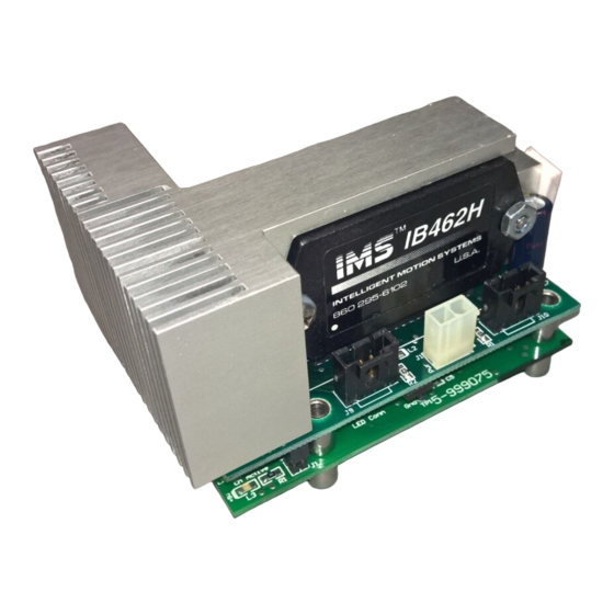
IMS IB462H Operating Instructions Manual (74 pages)
HIGH PERFORMANCE MICROSTEPPING DRIVE FEATURING THE INTERFACE BOARD AND THE VARIABLE SPEED CONTROL
Brand: IMS
|
Category: Control Unit
|
Size: 23 MB
Table of Contents
Advertisement

IMS IB462H Operating Instructions Manual (74 pages)
HIGH PERFORMANCE MICROSTEPPING DRIVE
Table of Contents
Advertisement