clare CLR-C1-PNL1 User Manual
Clareone wireless security and smart home panel
Hide thumbs
Also See for CLR-C1-PNL1:
- User manual (114 pages) ,
- Tech bulletin (3 pages) ,
- Quick start manual (2 pages)

Related Manuals for clare CLR-C1-PNL1


Summary of Contents for clare CLR-C1-PNL1
- Page 1 clareONE Wireless Security and Smart Home Panel User Manual Last modified: 10/21/19 DOC ID - 1871 • Rev 01 • DRAFT 00.07...
- Page 2 Clare Controls, LLC., except where specifically permitted under US and international copyright law. Trademarks and The clareONE name and logo are trademarks of Clare Controls, patents LLC. Other trade names used in this document may be trademarks or registered trademarks of the manufacturers or vendors of the respective products.
- Page 3 2006/66/EC (battery directive): This product contains a battery that cannot be disposed of as unsorted municipal waste in the European Union. See the product documentation for specific battery information. The battery is marked with this symbol, which may include lettering to indicate cadmium (Cd), lead (Pb), or mercury (Hg).
-
Page 5: Table Of Contents
Content Important information...ii Limitation of liability...ii Introduction...1 Packages contents...1 Installing the panel...1 clareONE setup wizard...12 clareONE Panel menus...21 clareONE menu bar...21 clareONE status bar...22 clareONE quick settings menu...23 Security...25 Security user management...26 Operating security...35 Favorites...40 Activity...44 Settings...45 Setting options...46 User Settings...50 Installer Settings...70 Emergency...90 Glossary...95... -
Page 6: Important Information
Important information Limitation of liability To the maximum extent permitted by applicable law, in no event will Clare Controls, LLC. be liable for any lost profits or business opportunities, loss of use, business interruption, loss of data, or any other indirect, special, incidental, or consequential damages under any theory of liability, whether based in contract, tort, negligence, product liability, or otherwise. -
Page 7: Introduction
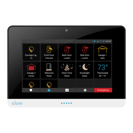
Introduction The clareONE Wireless Security and Smart Home Panel (CLR-C1-PNL1) is the Clare Controls all in one panel combines a smart home hub with a security panel. The clareONE is a smart home hub featuring customizable home automation and security control, eliminating the need for separate control and customization devices. - Page 8 Installation option 1: Desktop Option 1 uses the included kickstand. To desktop mount the panel: 1. Remove the panel’s back plate, exposing the battery. 2. Attach the power supply to the panel. Verify that the battery is plugged in. Note: For other power options, see Power options on page 11.
- Page 9 3. Attach the panel’s back cover, gently pressing it into place. 4. Press kickstand to the rear of the panel, and then slide the panel down. The stand slides into place, locking to the panel. 5. Plug the opposite end of the power supply into an electrical outlet. The tablet automatically powers up.
- Page 10 6. Connect the panel stand, and then slide the mount position to change the viewing angle. a. Press the tab in and slide the base to the desired position, locking it into place. Installation option 2: Wall mounted Option 2 uses the included wall mount bracket. Use the included screws and wall mount to mount the panel flush with the wall.
- Page 11 2. Remove the panel’s back plate, exposing the battery. 3. Attach the power supply to the panel. Verify that the battery is plugged in. 4. Attach the panel’s back cover, gently pressing it into place. clareONE...
- Page 12 5. Select an outlet or gang box. a. Outlet: Using 4 of the included screws and a power drill, securely attach the bracket to the wall. b. Gang box: Using 2 of the included screws, secure the bracket to the existing gang box.
- Page 13 To wall mount the panel using a remote 12VDC 3A supply: Note: Pictures to be added. 1. Place the mounting bracket against the wall, ensuring that it is in the desired location and close to an outlet. Select an outlet or gang box. a.
- Page 14 4. Using 2 of the included screws and a power drill, securely attach the bracket to the wall. 5. Remove the panel’s back plate, exposing the battery. clareONE...
- Page 15 6. Attach the power supply to the panel. Verify that the battery is plugged in. 7. Attach the panel’s back cover, gently pressing it into place. clareONE...
- Page 16 8. Press the panel onto the mounting bracket, and then slide the panel down until it locks into place. 9. Plug the opposite end of the power supply into an electrical outlet. The tablet automatically powers up. Note: Do not connect to a receptacle controlled by a switch. clareONE...
- Page 17 Power supply options Localized power Remote clareONE...
-
Page 18: Clareone Setup Wizard
clareONE setup wizard The clareONE panel comes with the ClareHome app pre-installed. Follow the setup wizard to connect to your home’s Wi-Fi and add sensors. To setup the panel: 1. Tap the screen. – or – Press the power button on the front of the panel. The Set Up Wizard displays. - Page 19 3. Select your time zone from the drop-down, and then tap Save. Note: ClareHome uses the location of the device for timers and events. 4. Tap the desired network, enter the password, and then tap OK. clareONE...
- Page 20 5. Tap Ok, and then add your sensors. The sensor management page displays. a. Tap Pair Sensor, and then select a learning method. clareONE...
- Page 21 b. Tap the sensor type. Learn Mode Tap Learn Mode, and then fault the sensor. The sensor pairs successfully. Manual Entry Tap Manual Entry. clareONE...
- Page 22 Enter the 7-digit TX ID found on the sensor. iii. Tap Next, and then tap Next. The sensor pairs successfully. clareONE...
- Page 23 c. Select the sensor’s name. d. Modify the sensor’s configuration as desired. e. Tap Add Sensor and add each sensor to the panel. 6. Tap Next to continue in the Wizard. clareONE...
- Page 24 7. Configure the users. a. Tap Add User, and then tap the desired user type. Note: The Master User PIN by default is set to 1234. We recommend changing this PIN. Do not forget this PIN, if lost or forgotten, the Master user becomes inaccessible.
- Page 25 Tap Custom, and then enter the username, then tap Save Name. c. Enter the desired User Passcode, tap Next, and then confirm the passcode. d. Configure each desired user, and then tap Next. clareONE...
- Page 26 For test descriptions, see System Test on page 81. 9. Add your Z-Wave devices to the panel. a. Tap Start, and then connect to the project using the Clare mobile app. For full device addition and configuration, see the ClareHome App Guide (DOC ID 1750).
-
Page 27: Clareone Panel Menus
clareONE Panel menus Use the following information to understand and navigate the clareONE panel. clareONE menu bar The clareONE panel menu bar options run along the bottom of the screen and features 4 icons with an Emergency button. This menu is available on any screen in the panel, allowing the user easy access to their most important panel features. -
Page 28: Clareone Status Bar
clareONE status bar The status bar displays the panel’s current volume, cellular connection, Wi-Fi, battery level, and time. Figure 3: Status bar Figure 4: clareONE status bar Icon Name Description The volume icon indicates the panel’s current volume. Volume The cellular icon indicates the panel’s current cellular status. Cellular The Wi-Fi icon indicates the panel’s current Wi-Fi strength. -
Page 29: Clareone Quick Settings Menu
clareONE quick settings menu The clareONE quick settings menu allows the user access more detailed information on the date, cellular connection strength, time and time zone, door chime toggle, Alexa toggle, Wi-Fi network name and strength, battery level percentage, volume slider, and screen brightness slider are available in the pull- down. - Page 30 To access the quick settings menu: 1. Tap and hold the status bar. 2. Swipe downward. To adjust the volume and brightness level: 1. Tap and slide volume/screen brightness indicator left (decreases volume/brightness) or right (increases volume/brightness). To enable/disable the door chime: 1.
-
Page 31: Security
The Security menu badge allows a user to quickly access their ClareHome security control and sensors. At a glance, users see the state of their security system and sensors. Note: Your security account must be created through your Clare Controls dealer. Figure 6: Security clareONE... -
Page 32: Security User Management
Security user management The security panel allows for individual user and duress codes. To create a security user: 1. Tap the Settings icon , and then tap User Settings. 2. Enter your user PIN. 3. Tap User Management. clareONE... - Page 33 4. Tap Add User. 5. Tap User. clareONE...
- Page 34 6. Select a user ID. – or – Tap Custom Name, enter the desired name, and then tap Save. 7. Enter the desired user Passcode, and then tap NEXT. clareONE...
- Page 35 You are prompted to confirm the Passcode. 8. Tap Next. 9. Select the expiration period, and then tap Save. Notes o The PIN will not work after the sect expiration period. o The expiration periods are 1 hour, 4 hours, 8 hours, 24 hours, 7 days, and unlimited (never expires).
- Page 36 The user is created successfully. To modify a user: 1. Access User Management. (Settings > User Settings > User Management). 2. Tap the Edit User icon. 3. Select the desired field to edit. 4. Modify each desired field. clareONE...
- Page 37 To create a duress code: 1. Access User Management. (Settings > User Settings > User Management). 2. Tap Add User, and then tap Duress Code. clareONE...
- Page 38 3. Enter the desired duress code, then tap Next. You are prompted to confirm the code again. 4. Tap Next. clareONE...
- Page 39 5. Select the expiration period, and then tap Save. Notes o The PIN will not work after the sect expiration period. o The expiration periods are 1 hour, 4 hours, 8 hours, 24 hours, 7 days, and unlimited (never expires). The duress code is created successfully.
- Page 40 To remove a security user or duress code: 1. Access User Management. (Settings > User Settings > User Management). 2. Tap the Delete icon next to the desired user/duress. 3. Tap Delete, and then tap Confirm. clareONE...
-
Page 41: Operating Security
Operating security The security panel allows the user to arm the panel in stay mode, arm the panel in away mode, disarm the panel, and contact an emergency service. To arm the panel: 1. Tap the Security Badge icon 2. Tap Arm Away. –... - Page 42 Notes o When selecting Arm Stay, the user has the option to instantly arm the panel. o When arming the alarm, you are given a default time of 30 seconds. If more time is needed, tap Add 30 Seconds. o Tap Cancel to stop the arming process, this requires a user PIN. 3.
- Page 43 To bypass a zone: Note: If a zone (sensor) is faulted (open), the panel cannot be armed until the zone is either no longer faulted, or the zone is bypassed. 1. Tap the Security Badge icon 2. Select an arming method (Arm Stay or Arm Away). 3.
- Page 44 2. Tap the Silent arm On/Off button. 3. Tap the desired arming method. 4. The panel continues to arm silently. Note: During a silent arm, the panel adds additional time and does not have a audible countdown (no beeps). clareONE...
- Page 45 To disarm the panel: 1. Tap the Security Badge icon 2. Tap Disarm. 3. Enter the PIN. clareONE...
-
Page 46: Favorites
Favorites The Favorites page allows the user to add frequently used devices and Scene tiles to the panel. Figure 7: Favorites Notes • When there are no favorites added to the page, only 1 row displays. Once an icon is added to the last space in a row, another row is added. •... - Page 47 To add a tile to favorite: 1. Tap an empty tile, and then tap the plus icon. 2. Tap the desired category. clareONE...
- Page 48 3. Tap the plus icon next to the desired device/Scene. The icon is added to the screen. clareONE...
- Page 49 To remove a tile from favorite: 1. Tap and hold the desired icon. 2. Tap Yes. clareONE...
-
Page 50: Activity
Activity The Activity page displays a list of your security events. This list includes the time and state or action of the panel (armed, disarmed, troubled, and faulted). Note: If the project has a camera, snapshots are provided. Figure 8: Activity Figure 9: clareONE activity icons Icon Name... -
Page 51: Settings
Settings The Settings page allows the user access and modify panel settings. Figure 10: Settings clareONE... -
Page 52: Setting Options
Setting options The below items are setting options the user can view and modify. Speaker The Speaker page allows the user to adjust the clareONE panel’s volume. Figure 11: Speaker To adjust the speaker settings: 1. Tap Settings, and then tap Speaker. 2. - Page 53 Display The Display page allows the user access to adjust the screen brightness. Figure 12: Display Display settings Display Timeout: This setting allows the user to adjust the length of time before the screen times out. Button LED: This setting allows the user to adjust the LED on the front of the panel.
- Page 54 Figure 13: User Settings For full User Settings, see User Settings on page 50. Installer Settings The Installer Settings page host a sub menu of advanced user settings. Note: The Installer Settings page can only be access with the Installer PIN. Figure 14: Installer Settings For full Installer Settings, see Installer Settings on page 70.
- Page 55 About The About page displays panel specific information including the firmware and hardware versions. Figure 15: About clareONE...
-
Page 56: User Settings
User Settings The User Settings page is a sub-menu of Settings. The User Settings page host settings for the master user. This page allows access to User Management, Wi- Fi management, Time Zone Settings, Security and Arming, Sensor Management, Restart, and Shutdown. Note: The Master PIN is required to access this menu. - Page 57 User Management The User Management page allows the user to add, modify, and remove panel users. Figure 17: User Management To add a user: 1. Tap the Settings icon , and then tap User Management. 2. Tap Add User. clareONE...
- Page 58 3. Select User (there are 3 user types). User types Master: The master user has access to all User Settings and is set by default. A second master user cannot be added. Duress Code: A user code that sends an emergency alert to the monitored central call station.
- Page 59 – or – Tap Custom Name, enter the desired name, and then tap Next. 5. Enter a user passcode, and then tap Next. clareONE...
- Page 60 6. Confirm the passcode, and then tap Next. 7. Select the expiration date. (1 hour, 4 hours, 8 hours, 24 hours, 7 days, or unlimited) 8. Tap Save. clareONE...
- Page 61 To create a duress code: 1. Tap the Settings icon , and then tap User Management. 2. Tap Add User. 3. Select Duress (there are 3 user types). User types Master: The master user has access to all User Settings and is set by default.
- Page 62 4. Enter the duress passcode, and then tap Next. 5. Confirm the passcode, and then tap Next. 6. Select the expiration date. (1 hour, 4 hours, 8 hours, 24 hours, 7 days, or unlimited) 7. Tap Save. clareONE...
- Page 63 To modify a user/duress code: 1. Access User Management. (Settings > User Settings > User Management). 2. Tap the Edit User icon. 3. Select the desired field to edit. clareONE...
- Page 64 To remove a user: 1. Access User Management. (Settings > User Settings > User Management). 2. Tap the Delete icon next to the desired user/duress. 3. Confirm by tapping Delete. clareONE...
- Page 65 The panel is now on the desired Wi-Fi network. To set the panel to AP Mode: AP Mode allows the user to set their panel in AP mode to use the Clare Controls Install Assist pp. Once turned on, the user sees the panel’s broadcasted network and a randomized passcode.
- Page 66 3. Tap AP Mode, and then tap ON. The panel is now in Ap mode. Time Zone The Time Zone page allows the user access to time zone selection. Figure 19: Time Zone To select a time zone: 1. Tap Settings, and then tap User Settings. clareONE...
- Page 67 2. Tap Time Zone, and then tap the Select Time Zone drop-down. 3. Scroll up or down to set the desired zone, and then tap Save. Security & Arming The Security & Arming page allows the user to modify their desired security settings.
- Page 68 Security & Arming settings Secure Arming: When enabled this setting requires that the user enter a PIN to arm the security panel. Transmission Delay: The time in seconds that the panel waits if an alarm is triggered before sending a transmission to the security central station. Exit Delay: The amount of time in seconds the panel waits for a user to exit the building before arming.
- Page 69 Sensor Management The Sensor Management page allows the user to add, modify, and remove panel sensors. Figure 21: Sensor Management To add a sensor: 1. Tap Settings, and then tap User Settings. 2. Tap Sensor Management, and then tap Add Sensor. clareONE...
- Page 70 3. Select Learn Mode. 4. Select the type of sensor. clareONE...
- Page 71 5. Trip the physical sensor. For example, move the door sensor’s pieces away from each other. 6. Select a name for the sensor, and the configure any desired sensor features. 7. Tap View Sensors to see the sensor in the list. –...
- Page 72 To modify the sensor: 1. Access Sensor Management. (Settings > User Settings > Sensor Management). 2. Tap the Edit Sensor icon. 3. Select the desired field to edit. clareONE...
- Page 73 To remove a sensor: 1. Access Sensor Management. (Settings > User Settings > Sensor Management). 2. Tap the Delete icon next to the desired sensor. 3. Confirm by tapping Delete. clareONE...
- Page 74 To create the Cross-Zone Group: Cross Zoning links 2 or more sensors together. If one of the sensors is tripped, and another sensor in that cross zone is tripped within the set time in this field, an alarm is sent Note: This is an advanced feature.
- Page 75 3. Scroll down to view Cross-Zone, and then tap Enabled. Restart The Restart page allows the user to restart the clareONE panel. Note: During the restart, the panel is not functional. Alarms and sensors are not active. Figure 22: Restart To restart the panel: 1.
-
Page 76: Installer Settings
To restart the panel after a shutdown: 1. Disconnect the panel’s battery, and then unplug the power supply. 2. Reconnect the battery, and then restore the power supply. The panel restarts. Installer Settings The Installer Settings page is a sub-menu of Settings. The Installer Settings page host settings for installers. - Page 77 The panel is now on the desired Wi-Fi network. To set the panel to AP Mode: AP Mode allows the installer to set their panel in AP mode to use the Clare Controls Install Assist pp. Once turned on, the user sees the panel’s broadcasted network and a randomized passcode.
- Page 78 3. Tap AP Mode, and then tap ON. The panel is now in Ap mode. Time Zone The Time Zone page allows the installer access to time zone selection. Figure 26: Time Zone To select a time zone: 1. Tap Settings, and then tap Installer Settings. clareONE...
- Page 79 2. Tap Time Zone, and then tap the Select Time Zone drop-down. 3. Scroll up or down to set the desired zone, and then tap Save. Security & Arming The Security & Arming page allows the installer to modify their desired security settings.
- Page 80 Security & Arming settings Secure Arming: When enabled this setting requires that the user enter a PIN to arm the security panel. Transmission Delay: The time in seconds that the panel waits if an alarm is triggered before sending a transmission to the security central station. Exit Delay: The amount of time in seconds the panel waits for a user to exit the building before arming.
- Page 81 Sensor Management The Sensor Management page allows the installer to add, modify, and remove panel sensors. Figure 28: Sensor Management To add a sensor: 1. Tap Settings, and then tap Installer Settings. 2. Tap Add Sensor. clareONE...
- Page 82 3. Select the type of sensor. 4. Tap Learn Mode. clareONE...
- Page 83 5. Trip the physical sensor. For example, move the door sensor’s pieces away from each other. 6. Tap View Sensors to see the sensor in the list. – or – Tap Add Sensor to add another sensor. To modify the sensor: 1.
- Page 84 2. Tap the Edit Sensor icon. 3. Select the desired field to edit. To remove a sensor: 1. Access Sensor Management. (Settings > Installer Settings > Sensor Management). 2. Tap the Delete icon next to the sensor. clareONE...
- Page 85 3. Confirm by tapping Delete. To create the Cross-Zone Group: Cross Zoning links 2 or more sensors together. If one of the sensors is tripped, and another sensor in that cross zone is tripped within the set time in this field, an alarm is sent.
- Page 86 2. Tap the Edit Sensor icon. 3. Scroll down to view Cross-Zone, and then tap Enabled. Restart The Restart page allows the installer to restart the clareONE panel. Note: During the restart, the panel is not functional. Alarms and sensors are not active.
- Page 87 To restart the panel: 1. Tap Settings, then tap Installer Settings. 2. Enter the User/Installer PIN. 3. Tap Restart, the confirm by tapping Restart Now. Shutdown - TBD The Shutdown page allows the installer to turn the panel off. Figure 30: Shutdown Insert image here To shut down the panel: 1.
- Page 88 Cellular Test The Cellular Test page displays the panel’s current cellular information. Figure 32: Cellular Test Sensor Test The Sensor Test page allows the user to check each sensor on their system. Triggering the sensor verifies that the sensor is currently communicating with the panel.
- Page 89 Siren Test The Siren Test page allows the user to check that a siren is working. Figure 34: Siren Test Touchscreen The Touchscreen page allows the user to verify that all panel display areas are touch sensitive. Note: To exit the touchscreen test, tap the same spot multiple times. Figure 35: Touchscreen clareONE...
- Page 90 WiFi Test The WiFi Test page allows the user to see their connected Wi-Fi and its status. Note: This test may take up to 60 seconds. Figure 36: WiFi Test Factory Reset This feature allows the user to default the panel. Note: When performing a factory reset, the panel loses all configured zones and users.
- Page 91 Demo Mode The mode allows the user to see a working demo of the panel. The user can add and remove favorite tiles, manage security, and see events. Figure 38: Demo Mode To enter Demo Mode: 1. Tap Settings, then tap Installer Settings. 2.
- Page 92 To exit Demo Mode: 1. Swipe the top bar downward. 2. Tap Exit Demo Mode. The panel restarts. Check for Updates The feature allows the user the ability to check for panel updates. This is used then an update has been dismissed or if the user is unsure of their current panel firmware.
- Page 93 To check for updates: 1. Tap Settings, then tap Installer Settings. 2. Enter the Installer PIN as prompted. 3. Tap Check for Updates. Note: If the panel is up to date you are not prompted to update. clareONE...
- Page 94 4. Tap Update Now. The update process begins. clareONE...
- Page 95 5. Once completed, leave update complete screen. Tap Settings or the desired page. clareONE...
-
Page 96: Emergency
Emergency The Emergency button is always available on the Menu bar. This button gives the user instant access to their emergency options. Use this button to contact the monitored central call station for an emergency. Figure 40: Emergency options Pressing the button takes the user to the Emergency screen, show in Figure 41: Emergency options. - Page 97 Call Auxiliary This button calls the monitored alarm station with an auxiliary emergency. Once pressed, it dials for the user. When the station answers, the screen changes, and the user can communicate with them through 2-way voice. Note: When the station is called using a silent alarm, 2-way communication is not available.
- Page 98 Call Police This button calls the monitored alarm station with a police emergency. Once pressed, it dials for the user. When station answers, the screen changes, and the user can communicate with them through 2-way voice. Note: When the station is called using a silent alarm, 2-way communication is not available.
- Page 99 Fire Alarm This button calls the monitored alarm station with a fire emergency. Figure 46: Emergency Police call clareONE...
-
Page 101: Glossary
Glossary Term Definition Bypass A state used to arm the security system when a zone (sensor) is faulted (open). Duress code A code that sends an emergency alert to the monitored central call station. Cross zone This settings links 2 or more sensors together. If one of the sensors is tripped, and another sensor in that cross zone is tripped within the set time in this field, an alarm is sent. -
Page 102: Appendices
Appendices Sensor installations and specifications A list of clareONE sensor installation and specifications are included as follows: • clareONE Keyfob Setup Sheet • clareONE Door/Window Sensor Installation Sheet • clareONE PIR Motion Sensor Installation Sheet clareONE... -
Page 103: Clareone Keyfob Setup Sheet
clareONE Keyfob Setup Sheet Part number: clareONE Keyfob (CLR-C1-KF) Description The clareONE Keyfob is a battery operated wireless handheld alarm sensor. When a button is pressed, the associated alarm is sent to the clareONE panel. Notes • The keyfob requires that each button is programed with the desired alarm call (police, fire, auxiliary, and silent). -
Page 104: Specifications
SOS: When tapping this button twice within 3 seconds, the keyfob sends a panic notification to the alarm monitoring station. To setup the keyfob: 1. Access the clareONE panel’s settings menu. 2. Tap User Settings or Installer Settings, and then enter the PIN code as prompted. Note: The user and Installer PIN codes are set to a default number until changed. -
Page 105: Clareone Door/Window Sensor Installation Sheet
clareONE Door/Window Sensor Installation Sheet Part number: clareONE Door/Window Sensor, White (CLR-C1-DW-W) clareONE Door/Window Sensor, Brown (CLR-C1-DW-B) Description The clareONE Door/Window Sensor is a magnetic sensor device designed to fit seamlessly alongside a door frame or windowsill. When the door or window are opened, the magnetic contact is disrupted, and the sensor transmits an alarm notification to the clareONE panel. - Page 106 Note: The sensor and magnet must be within .25 inch of each other on final installation. For gap range see, Table 1: Sensor and magnet gap range on page 101. 2. Remove the sensor’s battery pull tab. 3. Adhere sensor to the wall using the provided screws or adhesive. Note: The sensor should be attached to the unmoving part of the closure.
- Page 107 Sensor Management on page 75. 6. Once added, test the sensor. Look at the clareONE panel, and then open the door/window. Notice that the added sensor displays faulted. Note: Testing all sensors to the alarm monitoring station is strongly advised. Figure 47: Sensor and magnet axis TBD.
-
Page 108: Clareone Pir Motion Sensor Installation Sheet
clareONE PIR Motion Sensor Installation Sheet Part number: clareONE PIR Motion Sensor (CLR-C1-MOT) Description The clareONE PIR Motion Sensor is designed to fit seamlessly in the corner or the room or alongside a wall/door. When the PIR senses motion it transmits an alarm notification to the clareONE panel. -
Page 109: Pin Function
3. Adhere sensor to the wall using the provided screws or adhesive. Screws a. Gently remove the back plate from the sensor. b. Remove the circuit board, keeping the bug foam snug around the sensing element. c. Punch out the screw mounting holes. d. - Page 110 Detection length Default: 32.80 ft. (10 m) Optional: 19.68 ft. (6 m) Detection angle 90 degree Transmitted Tamper indications Low battery Pin function Sensitivity (2 stops) TBD Pet immunity (2 stops) TBD Test button Pairing, 2-minute test mode for motion Battery type CR123A (1300mAh) Battery life...
- Page 111 clareONE...
Need help?
Do you have a question about the CLR-C1-PNL1 and is the answer not in the manual?
Questions and answers