clare ClareOne CLR-C1-PNL1 User Manual
Wireless security and smart home panel
Hide thumbs
Also See for ClareOne CLR-C1-PNL1:
- User manual (112 pages) ,
- Tech bulletin (3 pages) ,
- Quick start manual (2 pages)

Related Manuals for clare ClareOne CLR-C1-PNL1


Summary of Contents for clare ClareOne CLR-C1-PNL1
- Page 1 ClareOne Wireless Security and Smart Home Panel User Manual Model CLR-C1-PNL1 Last modified: 02/20/20 DOC ID - 1871 • Rev 01...
- Page 2 Clare Controls, LLC., except where specifically permitted under US and international copyright law. Trademarks and The ClareOne name and logo are trademarks of Clare Controls, patents LLC. Other trade names used in this document may be trademarks or registered trademarks of the manufacturers or vendors of the respective products.
- Page 3 EU compliance EU directives 1999/5/EC (R&TTE directive): Hereby, Clare Controls, Llc. declares that this device is in compliance with the essential requirements and other relevant provisions of Directive 1999/5/EC. 2004/108/EC (EMC directive): Hereby, Clare Controls, Llc. Declares that this device is in compliance with the essential requirements and other relevant provisions of Directive 2004/108/EC.
-
Page 5: Table Of Contents
Content Important information...iii Limitation of liability...iii Introduction...1 Packages contents...1 Specifications...2 Installing the panel...4 ClareOne setup wizard...15 ClareOne Panel menus...18 ClareOne menu bar...18 ClareOne status bar...19 ClareOne quick settings menu...20 Security...22 Security user management...22 Operating security...22 Favorites...28 Activity...31 Settings...32 Display...32 User Settings...33 Installer Settings...34 About...34 User and Installer Settings...35... - Page 6 Emergency...61 Basic operation...65 Panel states...65 Panel LED...65 Maintenance...66 Contact...67 Evacuation plan...68 Glossary...71 Appendices...72 Quick reference...73 Trouble conditions...76 Panel zone list tracking...77 Sensor installations and specifications...79 ClareOne Keyfob Installation Sheet...80 ClareOne Door/Window Sensor Installation Sheet...84 ClareOne PIR Motion Sensor Installation Sheet...92 ClareOne Panic Pendant Installation Sheet...102 ClareOne...
-
Page 7: Important Information
Important information Limitation of liability To the maximum extent permitted by applicable law, in no event will Clare Controls, LLC. be liable for any lost profits or business opportunities, loss of use, business interruption, loss of data, or any other indirect, special, incidental, or consequential damages under any theory of liability, whether based in contract, tort, negligence, product liability, or otherwise. -
Page 9: Introduction
Introduction The ClareOne Wireless Security and Smart Home Panel (CLR-C1-PNL1) is a smart home hub featuring customizable home automation and security control. The ClareOne eliminates the need for separate control and customization devices. Package contents Note: Ensure all accessories are included. If not, contact the dealer. •... -
Page 10: Specifications
Specifications Touchscreen Size 7 in (18 cm) Resolution 1024 × 600 User Interface Status LED Multi-color Voice announcement System state, sensor state, disarm state User codes Up to 99 users and 10,000 possible codes Proximity sensor 5 ft (1.52 m) auto-wake up motion detection Radio/Network WiFi WiFi 802.11 a/b/g/n/ac dual band 2.4/5G... - Page 11 Figure 1: ClareOne Panel - front (1) Camera (3) Microphones (on each side) (2) IR sensors (2 on each side) (4) LED Figure 2: ClareOne Panel - exterior rear (1) Tamper button (6) DC routing hole #1 (2) Back plate secure screw (7) DC routing hole #2 (3) Rear panel cover (8) LAN routing hole...
-
Page 12: Installing The Panel
(4) Panel reset hole (8) Siren wiring terminal Installing the panel Only qualified installation technicians should install the panel. Clare Controls does not assume responsibility for damages caused by improper installation, connection to the network, or use of the device. - Page 13 Installation option 1: Desktop Option 1 uses the included kickstand. To desktop mount the panel: 1. Remove the panel’s back plate by pressing down on the 2 tabs and pulling the back plate outward, exposing the battery. 2. Route the power supply cable through the hole in the bottom right side of the kickstand.
- Page 14 4. Attach the panel’s back cover, gently pressing it into place. Verify that the tabs are both fully pressed in. 5. Press the sides of the back plate against the back of the panel, making sure there is no gap between the back plate and the panel. 6.
- Page 15 Installation option 2: Wall mounted Option 2 uses the included wall mount bracket. The recommended height for mounting the panel is 48 in. +/- 12 in. based on the comfort level of the end user. To wall mount the panel: 1.
- Page 16 5. Verify that the battery is plugged in, and then attach the power supply to the panel. 6. Attach the panel’s back cover, gently pressing it into place. 7. Press the sides of the back plate against the back of the panel, making sure there is no gap between the back plate and the panel.
- Page 17 Power supply options The ClareOne Panel has 2 power options: localized (using provided power supply with micro USB within 6 ft of the installation location) and remote (using CAT5/6 or 22AWG or thicker shielded security wire to extend the reach up to 100 ft from the installation location).
- Page 18 3. Carefully insert the negative end of the wire into the negative terminal of the DC power terminal. 4. Replace the back plate on the panel. 5. Connect the wires to the positive and negative terminals on the power supply. 6.
- Page 19 AC power. If the battery needs to be replaced, a replacement battery can be ordered using Clare Controls part number CLR-C1-BATT. The current battery capacity is displayed by the battery indicator in the Status Bar (Figure 9).
- Page 20 4. Insert the new battery’s header into the battery port on the panel 5. Gently place the battery into position with the battery’s cabling going above the battery in the back of the panel. 6. Return the panel’s back plate. Wired siren The ClareOne Panel has a 2 pin terminal connector to attach an external wired siren.
- Page 21 Figure 4: Wired siren connection (1) ClareOne Panel (4) Negative wire (5) Siren’s negative wire (2) Wired siren (6) Siren’s positive wire (3) DC Power supply Wired Ethernet The ClareOne Panel defaults to using WiFi for home network connection. However, a wired Ethernet connection is possible using the included USB-C Ethernet adapter.
- Page 22 Note: Do not use a non-Clare Controls SIM card. If a non-Clare Controls SIM card is used, the panel will not report correctly. Using a non-Clare Controls SIM card may result in a security risk. Figure 6: ClareOne Panel SIM card slot RESET button A recessed button is located under the panel’s back plate and can be used to...
-
Page 23: Clareone Setup Wizard
ClareOne setup wizard The ClareOne panel has the ClareHome app pre-installed. Follow the setup wizard to connect to the home’s WiFi and add sensors. To setup the panel: 1. Tap the screen. The Set Up Wizard displays. 2. Tap Start. 3. - Page 24 4. Scroll and tap to select the desired network, enter the password, and then tap Note: to hide the keyboard. 5. Add the desired sensors. For full sensor configuration and management, see Sensor Management on page 46. 6. Tap Next to continue in the wizard. 7.
- Page 25 9. Add desired Z-Wave devices to the panel. a. Tap Start. b. Connect to the project using the Clare mobile app. For full device addition and configuration, see the ClareHome App Guide (DOC ID 1750). 10. Tap Finish. ClareOne...
-
Page 26: Clareone Panel Menus
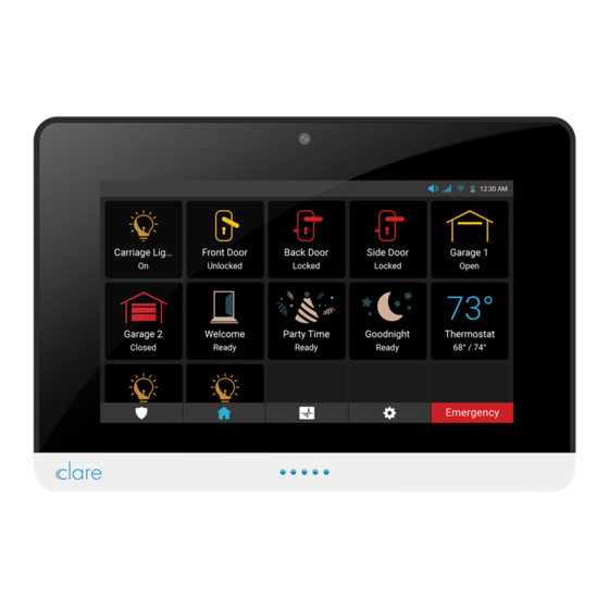
ClareOne Panel menus Use the following information to understand and navigate the ClareOne panel. ClareOne menu bar The ClareOne panel menu bar options run along the bottom of the screen and features 4 icons with an Emergency button. This menu is available on any screen in the panel, allowing easy access for the panel’s features. -
Page 27: Clareone Status Bar
ClareOne status bar The status bar displays the panel’s current volume, cellular connection, WiFi, battery level, and time. Figure 9: Status bar Table 3: ClareOne status bar Icon Name Description The volume icon indicates if the panel’s volume is on/off. Volume The cellular icon indicates the panel’s current cellular status. -
Page 28: Clareone Quick Settings Menu
ClareOne quick settings menu The ClareOne quick settings menu allows the user access more detailed information on the date, battery percentage, time, cellular connection strength, door chime toggle, Voice toggle, WiFi network name and strength, volume slider, and screen brightness slider. Figure 10: Quick settings menu Quick settings menu display Battery: The battery icon displays the panel’s current battery percentage. - Page 29 To access the quick settings menu: 1. Tap and hold the status bar. 2. Swipe downward. To adjust the volume and brightness level: 1. Tap and slide volume/screen brightness indicator left (decreases volume/brightness) or right (increases volume/brightness). To enable/disable the door chime: 1.
-
Page 30: Security
The Security menu badge allows a user to quickly access their ClareHome security control and sensors. Immediately, users see the state of their security system and sensors. Note: The security monitoring account must be created through the Clare Controls dealer. Figure 11: Security Security user management The panel allows for individual users and a duress code. - Page 31 The ClareOne panel supports Arm Stay and Arm Away (panel annunciation), and Silently Arm (no panel annunciation). When using Silently Arm, the exit time is doubled. • Violation, restoral, and then a second violation of an entry/exit zone prior to the end of the Exit Time restarts the Exit Time. The panel does not allow the Exit Time to be restarted more than once.
- Page 32 Tap Arm Stay. Notes o When selecting Arm Stay, the user has the option to instantly arm the panel. o When arming the alarm, you are given a default time of 60 seconds. If more time is needed, tap Add 30 Seconds. o Tap Cancel to stop the arming process, this requires a user PIN.
- Page 33 To bypass a zone: Note: If a zone (sensor) is faulted (open), the panel cannot be armed until the zone is either no longer faulted, or the zone is bypassed. 1. Tap the Security Badge icon 2. Select an arming method (Arm Stay or Arm Away). 3.
- Page 34 4. The panel continues to arm silently. Note: During a silent arm, the panel adds additional time and does not have an audible countdown (no beeps). To disarm the panel: 1. Tap the Security Badge icon 2. Tap Disarm. 3. Enter the PIN, and then tap Confirm. ClareOne...
- Page 35 To silence a trouble condition: 1. Tap the Security Badge icon When there is a trouble condition active, the security tab displays a Trouble Badge and a Microphone icon 2. Tap the Badge icon to see a list of trouble conditions. 3.
-
Page 36: Favorites
Favorites The Favorites page allows the user to add frequently used device and Scene tiles to the panel. Figure 12: Favorites Notes • When there are no favorites added to the page, only 3 rows display. Once an icon is added to the last space in a row, additional rows are added. •... - Page 37 2. Tap the desired category. 3. Tap the Plus icon next to the desired device/Scene. The icon is added to the screen. ClareOne...
- Page 38 To remove a tile from favorite: 1. Tap and hold the desired icon. 2. Tap Yes. ClareOne...
-
Page 39: Activity
Activity The Activity page displays a list of the security events. This list includes the time and state or action of the panel (armed, disarmed, troubled, and faulted). Note: The panel takes snapshots when activity occurs, or whenever a PIN code is entered. -
Page 40: Settings
Settings The Settings page allows the user access to modify panel settings. Figure 14: Settings The below items are setting options the user can view and modify. Display The Display page allows the user access to adjust screen settings. Figure 15: Display ClareOne... -
Page 41: User Settings
Display settings Display Timeout: This setting allows the user to adjust the length of time before the screen times out. Screen Cleaning: This setting allows the user 1 minute to clean the panel’s screen. During this time, the screen is not touch sensitive. Temperature Mode: This setting allows the user to select Fahrenheit or Celsius for their thermostat display. -
Page 42: Installer Settings
Installer Settings The Installer Settings page hosts a sub menu of advanced settings. Note: The Installer Settings page can only be accessed with the Installer PIN. Figure 17: Installer Settings For full Installer Settings, see User and Installer Settings on page 35. About The About page displays panel specific information including the firmware, hardware versions, and network settings. -
Page 43: User And Installer Settings
User and Installer Settings The User and Installer Settings pages are sub-menus of Settings. The User Settings page hosts settings for the master user and the Installer Settings page hosts advanced settings for the installer. The User Settings menu has access to User Management and the Installer Settings menu has access to Panel Reset, and Demo Mode. -
Page 44: User Management
User Management Note: User Management is only accessible in the User Settings menu. The User Management page allows the user to add, modify, and remove panel users. Figure 21: User Management To add a user: 1. Tap the Settings icon 2. - Page 45 4. Select User (there are 3 user types). User types Master: The master user has access to all User Settings and is set by default. Note: The Master User can only be modified, a second master user cannot be added. Duress Code: A user code that sends an emergency alert to the monitored central station.
- Page 46 Tap Custom Name, enter the desired name, and then tap Next. 6. Enter a user passcode, and then tap Next. 7. Confirm the passcode, and then tap Next. ClareOne...
- Page 47 8. Select the expiration date. (1 hour, 4 hours, 8 hours, 24 hours, 7 days, or unlimited) 9. Tap Save. To create a duress code: Notes • Only 1 duress code can be added to the panel. • Duress is disabled by default. Once a Duress user is created, duress is enabled.
- Page 48 4. Select Duress Code. Note: The ClareOne panel only supports one Duress user. 5. Enter the desired code, and then tap Next. 6. Confirm the passcode, and then tap Next. 7. Tap Save. ClareOne...
- Page 49 To modify a user/duress code: 1. Access User Management. Settings > User Settings >Enter master PIN > User Management 2. Select the desired user/duress, and then tap the Edit User icon. 3. Select the desired field to edit. To remove a user: 1.
-
Page 50: Wifi
2. Tap the Delete icon next to the desired user/duress. 3. Confirm by tapping Delete. WiFi The WiFi page allows the user/installer access to the available WiFi networks and their corresponding strengths. Figure 22: WiFi To change WiFi networks: 1. Tap the Settings icon 2. -
Page 51: Time Zone
To set the panel to AP Mode: AP Mode allows the user to set their panel in AP mode to use the Clare Controls Install Assist app. Once turned on, the user sees the panel’s broadcasted network and a randomized passcode. -
Page 52: Security & Arming
To select a time zone: 1. Tap Settings, and then tap User Settings/Installer Settings. 2. Enter the Master/Installer PIN, and then tap Time Zone. 3. Tap the Select Time Zone drop-down. 4. Scroll up or down to set the desired zone, and then tap Save. Security &... - Page 53 Security & Arming settings Secure Arming: When enabled this setting requires that the user enter a PIN to arm the security panel. Transmission Delay: The time in seconds that the panel waits if an alarm is triggered before sending a transmission to the security central station. Exit Delay: The amount of time in seconds the panel waits for a user to exit the building before arming.
-
Page 54: Sensor Management
Sensor Management The Sensor Management page allows the user/installer to add, modify, and remove panel sensors. For a full sensor list and individual sensor settings, see ClareOne Sensors Integration Notes (DOC ID 1931). Figure 25: Sensor Management To add a sensor: 1. - Page 55 4. Select Learn Mode. 5. Select the type of sensor. 6. Trip the physical sensor. For example, move the door’s sensor and magnet away from each other. 7. Select a name for the sensor, and then configure any desired sensor features.
- Page 56 To modify the sensor: 1. Access Sensor Management. (Settings > User/Installer Settings > Enter user/installer PIN > Sensor Management). 2. Tap the Edit Sensor icon. 3. Select the desired field to edit. To remove a sensor: 1. Access Sensor Management. (Settings > User/Installer Settings> Enter user/installer PIN >...
- Page 57 2. Tap the Delete icon next to the desired sensor. 3. Confirm by tapping Delete. To create the Cross-Zone Group: Cross Zoning links 2 or more sensors together. If one of the sensors is tripped, and another sensor in that cross zone is tripped within the set time in this field, an alarm is triggered.
- Page 58 2. Tap the Edit Sensor icon. 3. Scroll down to view Cross-Zone, and then tap Enabled. 4. Repeat steps 2 through 3 for each zone to be added to the cross-zone. ClareOne...
- Page 59 Modifying sensor settings Each ClareOne sensor can be adjusted for user preference. Use the steps below to access Sensor Management. For full sensor setting information, see ClareOne Sensors Integration Notes (DOC ID 1931). Note: These settings should not be adjusted without proper security experience and knowledge.
-
Page 60: Restart
Restart The Restart button allows the user/installer to restart the ClareOne panel. Note: During the restart, the panel is not functional. Alarms and sensors are not active. Figure 26: Restart To restart the panel: 1. Tap Settings, and then tap User Settings/Installer Settings. 2. - Page 61 Figure 27: System test To test the panel: 1. Unplug the panel from the wall outlet. 2. Look at the displayed panel state, verify that it is in normal standby mode with no current alarms. 3. Fault/open one of the paired sensors. The panel vocalizes that the sensor is not ready, and the faulted sensor is now marked not ready on the Security page.
- Page 62 Cellular Test The Cellular Test page displays the panel’s current cellular information. Figure 28: Cellular Test Sensor Test The Sensor Test page allows the user to check each sensor on their system. Triggering the sensor verifies that the sensor is currently communicating with the panel.
- Page 63 Siren Test The Siren Test page allows the user to check that a siren is working. Figure 30: Siren Test Touchscreen The Touchscreen page allows the user to verify that all panel display areas are touch sensitive. Note: To exit the touchscreen test, tap the same spot 3 times. Figure 31: Touchscreen ClareOne...
-
Page 64: Check For Updates
WiFi Test The WiFi Test page allows the user/installer to see their connected WiFi and its status. Note: This test may take up to 60 seconds. Figure 32: WiFi Test Check for Updates The feature allows the user/installer the ability to check for panel updates. This is used when an update has been dismissed or if the user is unsure of their current panel firmware. - Page 65 To check for updates: 1. Tap Settings, then tap User/Installer Settings. 2. Enter the Master/Installer PIN as prompted. 3. Tap Check for Updates. Note: If the panel is up to date you are not prompted to update. 4. Tap Update Now. ClareOne...
-
Page 66: Panel Reset
The update process begins. 5. Once completed, leave Update Complete screen. Tap Settings or the desired page. Panel Reset This feature allows the user to default the panel. Notes • Panel Reset is only available in Installer Settings. • When performing a panel reset, the panel loses all configured zones, users, and time zone settings. -
Page 67: Demo Mode
Figure 34: Panel Reset To reset the panel: 1. Tap Settings, then tap Installer Settings. 2. Enter the Installer PIN as prompted. 3. Tap Panel Reset. 4. Read through the warning popover, and then tap Panel Reset. Demo Mode The mode allows the user to see a working demo of the panel. The user can add and remove favorite tiles, manage security, and see events. - Page 68 Figure 35: Demo Mode To enter Demo Mode: 1. Tap Settings, then tap Installer Settings. 2. Enter the Installer PIN as prompted. 3. Tap Demo Mode. 4. Tap tiles and icons to operate the corresponding devices. To exit Demo Mode: 1.
-
Page 69: Emergency
Emergency The Emergency button is always available on the Menu bar. This button gives the user instant access to emergency options. Use this button to contact the monitored central call station for an emergency. Figure 36: Emergency options Pressing the button takes the user to the Emergency screen, shown in Figure 37: Emergency options. - Page 70 Police Panic This button calls the monitored alarm station with a police emergency. Once pressed, it dials for the user. When the station answers, the screen changes, and the user can communicate with them through two-way voice. Note: When the station is called using a silent panic, two-way communication is not available.
- Page 71 Fire Panic This button sends an immediate fire panic to the central station. Figure 40: Emergency Fire Panic Auxiliary Panic This button calls the monitored alarm station with an auxiliary emergency. Once pressed, it dials for the user. When the station answers, the screen changes, and the user can communicate with them through two-way voice.
- Page 72 Figure 42: Emergency Auxiliary connection ClareOne...
-
Page 73: Basic Operation
Basic operation This section covers the basic operation of the ClareOne Panel, including terms and maintenance recommendations. Panel states The ClareOne Panel has multiple states. Each state has a different effect on the panel and user access. Normal Standby: This is the normal state of the panel. In this state everything is accessible for the user/installer when using the proper PIN codes. -
Page 74: Maintenance
Maintenance The panel should be used and tested weekly. Testing should include validating communication between sensors and panel, verifying the alarm functions properly, validating operation on battery, and checking that communication networks are operational. For panel and sensor testing, see System Test, on page 52. For battery maintenance, see Panel battery specifications and maintenance, on page 11. -
Page 75: Contact
Local Dealer Phone Number: _______________________________ Local Dealer Email: _______________________________________ Monitoring Center Phone Number: ___________________________ NOTE TO INSTALLER: PLEASE ATTACH BUSINESS CARD OR STICKER WITH CONTACT INFO HERE If there is no information provided above, contact: Clare Technical Services 941.404.1072 ClareSupport@clarecontrols.com ClareOne... -
Page 76: Evacuation Plan
Evacuation plan It is recommended that everyone have an evacuation plan to get away safely in the event of a fire or emergency. Create an evacuation plan for safety. See the National Fire Protection Association’s (NFPA) evacuation information. https://www.nfpa.org/Public-Education/Staying-safe/Preparedness/Escape- planning NFPA has recommended the following planning tips and action plans: Escape planning tips •... - Page 77 If windows or doors in your home have security bars, make sure that the bars have emergency release devices inside so that they can be opened immediately in an emergency. Emergency release devices won't compromise your security - but they will increase your chances of safely escaping a home fire. •...
- Page 78 • Always choose the escape route that is safest – the one with the least amount of smoke and heat – but be prepared to escape under toxic smoke if necessary. When you do your fire drill, everyone in the family should practice getting low and going under the smoke to your exit.
-
Page 79: Glossary
Glossary Term Definition Bypass A state used to arm the security system when a zone (sensor) is faulted (open). Duress code A code that sends an emergency alert to the monitored central call station. Cross zone This setting links 2 or more sensors together. If one of the sensors is tripped, and another sensor in that cross zone is tripped within the set time in this field, an alarm is sent. -
Page 80: Appendices
Appendices The below items are included in the ClareOne manual for user convenience. Quick reference...73 Trouble conditions...76 Panel zone list tracking...77 Sensor installations and specifications ...79 ClareOne Keyfob Installation Sheet...80 ClareOne Door/Window Sensor Installation Sheet...84 ClareOne PIR Motion Sensor Installation Sheet...92 ClareOne Panic Pendant Installation Sheet...102 ClareOne... -
Page 81: Quick Reference
Quick reference The following information on the ClareOne panel is provided in quick reference form for user convenience. Table 5: Quick reference Feature Quick reference info Exit Delay is the time in seconds that the panel waits if an alarm is triggered before sending a transmission to the security central station. - Page 82 Alarms may be silenced by entering a single user PIN. The panel alarm silences after entering the first PIN digit but will resume if PIN Disarm (abort) entry is aborted. Refer to Operating Security on page 22. This feature enables/disables the ability to use a duress code. Duress codes may still be created in User Settings.
- Page 83 6. The installer should record all test results for the dealer and homeowner/user records. 7. The installer should contact the central station according to central station testing policy and inform them that they have completed testing for the specific account. ClareOne...
-
Page 84: Trouble Conditions
Trouble conditions This is a list of all possible trouble conditions for the panel and zones/sensors. Table 6: Trouble conditions Condition Description Audible alert “Zones low battery” Zone(s) Low Battery The sensor/zone has a low battery. “No battery” The panel battery is not detected or Missing Battery installed. -
Page 85: Panel Zone List Tracking
Panel zone list tracking Print these pages out for the installer to use for panel zone tracking. For a separate copy of this sheet, see ClareOne Panel Zone Tracking (DOC ID 1930). Zone # Name Zone # Name ClareOne... - Page 86 Zone # Name Zone # Name ClareOne...
-
Page 87: Sensor Installations And Specifications
Sensor installations and specifications Note: The maximum distance over which a sensor and the panel can communicate may be reduced when the equipment is installed in a typical home. Placement of the sensor, building materials and construction, location of mirrors and other RF interfering/blocking devices can all reduce the overall range. -
Page 88: Clareone Keyfob Installation Sheet
ClareOne Keyfob Installation Sheet Part number: CLR-C1-KF Description The ClareOne Keyfob is a battery operated wireless handheld alarm sensor. When a button is pressed, the associated command is sent to the ClareOne panel. Notes • The keyfob requires that each button is programed with the desired command (Away, Stay, Disarm, and SOS). - Page 89 Button function The keyfob has 4 buttons. Once the keypad is added to the panel, the buttons controls the arming and disarm features of the panel. Away: When tapping this button, the panel arms in Away mode. Stay: When tapping this button, the panel arms in Stay mode. Disarm: When tapping this button, the panel is disarmed.
- Page 90 3. Slide a fingernail/fingertip into the keyfob’s bottom slot (area with the keychain protruding), and then push the keyfob’s back casing upward and away from the front of the keyfob. Note: The keychain will come lose in this process, be careful not to lose the keychain.
- Page 91 Specifications Compatible panel ClareOne Transmitter frequency 433MHz TX Encrypted Buttons 4 Buttons • Away • Stay • Disarm • LED indication 1 LED (red) Battery type CR2032 (220mAh) Battery life 5 years Sensor dimensions 1.49 × 2.53 × .55 in. (W ×...
-
Page 92: Clareone Door/Window Sensor Installation Sheet
ClareOne Door/Window Sensor Installation Sheet Part number: ClareOne Door/Window Sensor, White (CLR-C1-DW-W) ClareOne Door/Window Sensor, Brown (CLR-C1-DW-B) Description The ClareOne Door/Window Sensor is a magnetic sensor device designed to fit seamlessly alongside a door frame or window frame. When the door or window are opened, the magnetic contact is disrupted, and the sensor transmits an alarm notification to the ClareOne panel. - Page 93 Figure 43: Sensor orientation The sensors and magnet each have a slightly engraved line. This line denotes where the sensor and magnet align to function properly. If the sensor and magnet, when together/closed, do not line up correctly, the sensor will not report correctly.
- Page 94 Sensor screws 3.1.a Locate the bottom of the sensor (the slotted short end). 3.1.b Turn the sensor over, and then gently slide a fingernail/fingertip into the slot pushing the sensor’s back plate up and away from the sensor body. 3.1.c (Optional) Mark the screw hole locations, then using a power drill, drill holes and install the 2 provided wall anchors.
- Page 95 3.1.h Observe the sensor position. When satisfied with position, use a screwdriver to fully secure each screw in the wall. 3.1.i Press the front of the sensor against the base, until there is an audible snap. Sensor adhesive 3.2.a Select the desired position for the sensor. 3.2.b Peel one side of the adhesive tape, and then press the tape firmly against the sensor.
- Page 96 4.1.c (Optional) Mark the screw hole locations, then using a power drill, drill holes and install the 2 provided wall anchors. 4.1.d Remove the adhesive’s film cover, and then place the back plate against the door/window, making sure that the orientation and alignment are correct for the desired position.
- Page 97 4.2.b Peel one side of the adhesive tape, and then press the tape firmly against the magnet. Note: Once the adhesive is secure, the sensor cannot be moved. 4.2.c Peel the other side of the adhesive, and then press the magnet against the wall.
- Page 98 WARNING: If an incompatible replacement battery is used, or the battery is installed incorrectly explosion or damages may occur. AVERTISSEMENT: Si une batterie de remplacement incompatible est utilisée ou si la batterie est installée de manière incorrecte, une explosion ou des dommages peuvent survenir.
- Page 99 5. Use a fingernail/fingertip to push the battery out of the casing, noting the polarity of the battery. 6. Slide a new CR2032 battery into the battery casing, making sure that the polarity is correct. 7. Press the circuit board back into the sensor casing until secure. There will be an audible snap.
-
Page 100: Clareone Pir Motion Sensor Installation Sheet
ClareOne PIR Motion Sensor Installation Sheet Part number: CLR-C1-PIR Description The ClareOne PIR Motion Sensor is designed to fit seamlessly in the corner or the room or alongside a wall/door. When the PIR senses motion it transmits an alarm notification to the ClareOne panel. Important safety instructions Before you install this sensor, be sure to: •... - Page 101 3. Add the sensor to the panel. See Sensor Management on page 46. Note: You must press and hold the button on the side of the sensor to pair the sensor to the panel. 4. Adhere the sensor to the wall using the provided screws or adhesive. Note: We recommend using the provided screws for installation.
- Page 102 4.1.d Remove the adhesive film cover, and then place the back plate against the wall, making sure that the orientation is correct for the desired position. Note: Once placed the sensor cannot be moved without damaging the adhesive. 4.1.e Insert the included mounting screw into the screw breakaway screw hole, using a screwdriver to fully secure the backplate to the wall.
- Page 103 Adhesive 4.2.a Locate the bottom of the sensor (the slotted flat end), and then use a screwdriver to remove the casing’s screw. 4.2.b Gently slide a fingernail/fingertip into the slot and push the top casing of the sensor upward. 4.2.c Set the PINs and jumpers to the desired position. See Pin function, on page 98.
- Page 104 5. Once added, test the sensor. Look at the ClareOne panel, and then cause motion in front of the sensor. Notice that the added sensor displays faulted. Note: Testing all sensors with the alarm monitoring station is strongly advised. Figure 45: Sensor range and detection Battery replacement The ClareOne PIR Motion Sensor requires a CR123A battery.
- Page 105 2. Gently slide a fingernail/fingertip into the slot and push the top casing of the sensor outward, away from the wall. 3. Use a fingernail/fingertip to push the battery out of the casing, noting the polarity of the battery. 4. Slide a new CR123A battery into the battery casing, making sure that the polarity is correct.
- Page 106 Pin function The PIR Motion Sensor has 2 sets of adjustable pins. The pins adjust the Pet Immunity setting and the Sensitivity level. Each set of pins has 2 settings that can be selected. Figure 46: Sensor pins and tamper switch (1) Pet immunity pins (3) Sensitivity pins (2) Tamper switch...
- Page 107 Pet immunity The pet immunity pins allow the user to select the desired immunity level. Place the selector over the desired pin configuration. To change the pet immunity level: 1. Remove the back plate from the motion sensor. 2. Turn the sensor over so the battery faces up. 3.
- Page 108 3. Locate the sensitivity pins on the right side. 4. Gently pinch the jumper and pull upward and away from the sensor. All 3 pins are visible. 5. Gently press the jumper on the desired pin set. 6. Replace the sensor plate, and then continue to installation. –...
- Page 109 Specifications Compatible panel ClareOne Transmitter frequency 433MHZ TX Encrypted Pet immunity 33 to 55lb dog Detection length Default: 32.80 ft. (10 m) Optional: 19.68 ft. (6 m) Detection angle 90 degree Mounting height 7.5 to 9.5 ft. (2.28 to 2.89 m) Transmitted indications Tamper Low battery...
-
Page 110: Clareone Panic Pendant Installation Sheet
ClareOne Panic Pendant Installation Sheet Part number: CLR-C1-PNC Description The ClareOne Panic Pendant is a lithium battery operated wireless handheld panic device for the ClareOne Panel system. When the button is pressed, a wireless signal is sent to the panel, setting the panel to Panic. Notes •... - Page 111 Button function The pendant has 1 button. Once the pendant is added to the panel, the button, when pressed, sends a wireless alert to the panel. This alert sets the panel to Panic. If the ClareOne Panel has a monitoring service, the central station is notified.
- Page 112 3. Use a fingernail/fingertip to push the battery out of the casing, noting the polarity of the battery. 4. Slide a new CR2032 battery into the battery casing, making sure that the polarity is correct. 5. Press the pendant backplate into place. 6.
Need help?
Do you have a question about the ClareOne CLR-C1-PNL1 and is the answer not in the manual?
Questions and answers