Table of Contents
Advertisement
Quick Links
Advertisement
Table of Contents

Related Manuals for SEM Breaktank


Summary of Contents for SEM Breaktank
- Page 1 Handbook SEM Compact Breaktank with Level Control The specialist for safe & clean swimming water SEM Waterbehandeling B.V. Telefoon: +31 (0) 40 257 03 40 De Run 4420 sem@semwaterbehandeling.nl 5503 LR Veldhoven www.semwaterbehandeling.nl Netherlands...
- Page 3 Breaktank 6-2015 art.nr.:2502925 EN1717/EN13077...
-
Page 4: Table Of Contents
............................15 ETTING PARAMETERS 4. MAINTENANCE AND SERVICE ........................16 5. FAILURES ..............................17 6. TECHNICAL SPECIFICATIONS ........................18 SEM B .:2502925 ........................18 REAKTANK ART 7.SPARE PARTS ............................... 18 8. ASSEMBLE AND START USING OPTIONS ..................... 19 06/2015 V4.0... -
Page 5: For Information
A N D B O O K For information The Breaktank of SEM water treatment B.V.is a universal breaktank that is specially designed for the supplementation (adding fresh water) of swimming pools. This break tank ensures the necessary interruption between (drinking) water and swimming pool water. Under no circumstances can water flow from the pool back into the water supply network, not even when the pressure on the grid ceases. - Page 6 A N D B O O K The SEM Breaktank can be used for the supplementation of a pool. By default, the SEM break tank is equipped with a universal level control which can measure 1 level. A float switch is supplied to measure the level in the skimmer or measuring tube.
-
Page 7: Introduction
If the level is too low, the pump will start and fresh water will be added. The construction of the Breaktank is such that swimming pool water can never flow back into the pipeline network (mandatory by the water company). The water supply network must never be operated by a closed system connected to the pool. -
Page 8: Control
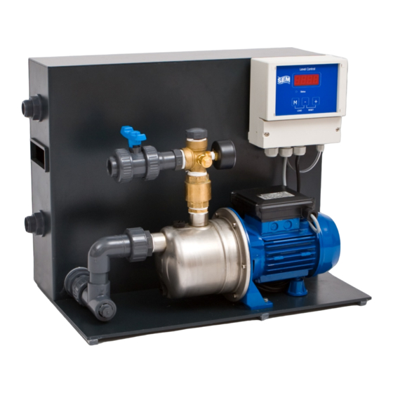
Q / H curve and does not suffer any damage due to overload or cavitation. The pump pressure can be read on the mounted pressure gauge. 2.1 Display and buttons The SEM Compact Breaktank is equipped with a digital display. The display shows all relevant information. STATUS... - Page 9 R E A K T A N K A N D B O O K Alarm notifications: All alarm messages can be reset by pressing at the same time, as soon as the fault has been rectified. Status light: The status light is green when the pump is in operation. In the event of a fault, this light will flash red. = green, pump in operation = red flashing, fault, the fault code on the display indicates the nature of the fault.
-
Page 10: Service Menu
R E A K T A N K A N D B O O K 2.2. Service menu The service menu is opened by the button press for > 3 seconds. The decimal point on the right of the display flashes to indicate that the service menu is active. The menu can be followed by a short press on the button. -
Page 11: Setup Menu
R E A K T A N K A N D B O O K 2.3 Setup menu The setup menu is opened from the service menu. The service menu can be opened to push the the button >3 seconds. On the right of the display, the decimal point changes from flashing to continuous edges to indicate that the setup menu is active. - Page 12 C=0..50% (10) With this factor the measured value of the level sensor of the tank (pressure sensor) can be corrected. Note: changing this factor influences the operation of the break tank. Only change in consultation with SEM Waterbehandeling B.V. 06/2015 V4.0...
-
Page 13: Schematic Representation Of Menu Structure
R E A K T A N K A N D B O O K 2.4 Schematic representation of menu structure 06/2015 V4.0... -
Page 14: Installation Guidelines
SEM Water Treatment within 4 working days. 3.1 Hydronic installation • Place the Breaktank on a flat surface or use the optional wall mounting bracket. Preferably in the vicinity of a wall socket (230V), a cold water faucet and a sewer connection. •... -
Page 15: Electrical Installation
• Provide a wall socket near the Breaktank. Since the break tank is often located in a damp room (such as boiler houses and engine rooms), it is wise to choose a spray-free type. It is recommended to connect the Breaktank behind an earth leakage switch. - Page 16 This is a calibration of the measuring system. If the level is still not 210mm (+/- 5mm), please contact SEM Waterbehandeling B.V. After this check the break tank is ready for use. •...
- Page 17 R E A K T A N K A N D B O O K Characteristics of the feed pump Compact break tank 06/2015 V4.0...
-
Page 18: Setting Parameters
R E A K T A N K A N D B O O K 3.4 Setting parameters The following parameters are set as standard on the PLC unit at the factory: Ta= 3 Tb=15 Tc=1 ... -
Page 19: Maintenance And Service
(especially when mounting in a skimmer, for example). From time to time the float should therefore be inspected. • Spare parts are always available at SEM Water Treatment. • The operating hours of the pump can be read in the service menu. -
Page 20: Failures
If not, replace the cabling or float. In case of other malfunctions contact SEM Water Treatment Technical Department. Equipment that is contaminated with chemicals or toxic substances that are hazardous to health is not considered by SEM Water Treatment! -
Page 21: Technical Specifications
Dimensions (lxbxh) 500 x 340 x 450 mm Weight 10 kg 7.Spare parts Article Description Articlenumber Pump for breaktank, type JESXM 5 230V/0,37kW 5305010 Float switch SEM (switch) with 10m cable 6022011 Selonoid valve ½” 3113012 Float 1/2" for breaktank (with white ball) -
Page 22: Assemble And Start Using Options
800 l / hour. This also limits the maximum capacity of the Breaktank at 800 l / h. By replacing this float valve with a solenoid valve ½ "the filling capacity is increased to about 1500 l / h. The installation of this option is as follows: •... - Page 23 Now mount in the pipe bend with ½ "M in the tank grommet (5) (see photo below). Use Teflon tape for this. Now mount the solenoid valve (8) on the outside of the Breaktank (8) using the double nipple •...
- Page 24 KLEP1 (+ 24V + brown) and OUT (- blue) of the control box. See also the connection diagram below. • The Breaktank can now be put into operation. Possibly the parameters Ha and Hb can be adjusted. These are already correct from the factory. 06/2015 V4.0...
- Page 25 R E A K T A N K A N D B O O K Notes: 06/2015 V4.0...
Need help?
Do you have a question about the Breaktank and is the answer not in the manual?
Questions and answers