Table of Contents

Related Manuals for Viewpro Mini Z10TIRM


Summary of Contents for Viewpro Mini Z10TIRM
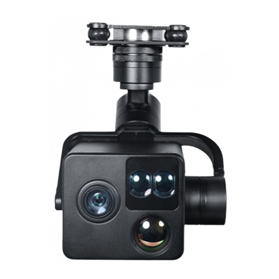
- Page 1 Mini Z10TIRM 10x Optical Zoom EO + IR Dual-Sensor Laser Rangefinder Object Tracking Gimbal Camera User Manual Standard Version Viewport Version 标准版 快拆版 For more details please scan the QR code or visit our website: www.viewprotech.com...
-
Page 2: Disclaimer And Warning
Viewpro product. Disassemble the gimbal camera by user is not permitted, which may cause the camera does not to work normally. Viewpro accepts no liability for damage, injury or any legal responsi- bility incurred directly or indirectly from the use of this project. The user shall observe safe and lawful practices including, but not limited to, those set forth in the manual. -
Page 3: Standard Version
The integrated design of damping system and gimbal can greatly reduce mechanical vibration. Mini Z10TIRM is widely used in UAV industries of public security, electric power, fire fighting, zoom aerial photography and other industrial applications. - Page 4 B. Viewport Version USB to TTL Cable Gimbal Camera x 1 pc x 1 pc Copper Cylinder M3 Screw x 4 pcs x 8 pcs Power Cable x 1 pc PWM Control Cable x 1 pc TTL / S.BUS Control Cable x 1 pc TTL Connect Cable x 3 pcs...
-
Page 5: Installation Instruction
2. Installation Instruction 2.1 Overview [12] [14] [10] [13] Control Box Back Side (Standard Version) [11] [12] [15] [14] Viewport [13] (Viewport Version) - Page 6 [1] Control box [9] TF card slot [2] Upper damping board [10] Roll axis motor [3] Lower damping board [11] Pitch axis motor [4] laser rangefinder [12] 3-6S power interface [5] FHD zoom camera [13] Micro HDMI interface [6] Infrared thermal camera [14] Ethernet interface [7] Damping ball [15] Viewport unlock button...
- Page 7 The input voltage cannot be higher than 6S. The pin insertion interface cannot be connected with power supply. The yellow jumper cap cannot be removed. 2.2.2 Control Box Printing (Viewport Version) Front Side POWER Left Side ETHERNET UART & S.BUS Right Side...
- Page 8 2.3.1 Device Dimensions (Standard Version) Unit: mm 119.4 105.7...
- Page 9 2.3.2 Device Dimensions (Viewport Version) Unit: mm 43.2 34.3 48.4...
- Page 10 2.4 Install Mounting Part (1) Find out the arrow on the gimbal which indicating the yaw heading of the payload (i.e. the lens direction when the camera power on), and synchronize with the direction specified by the UAV. (2) Fix one end of the copper cylinder on the screw hole of lower damping board, and use M3 screw to fasten it.
- Page 11 2.5 Viewport Release Instruction × 1. Make sure the two white stripes indicated in above picture are aligned with each other. (If the stripes are not aligned to each other, please pinch the connector part and turn it to left manually)
- Page 12 2. Align the white dot (unlock icon) to the red triangle (below unlock button), push the gimbal into the Viewport completely and then rotate the gimbal camera anticlockwise. 3. When you hear "click" sound (when red dot is aligned to the red triangle) means the gimbal camera and Viewport has been locked.
-
Page 13: Install Tf Card
2.6 Install TF Card TF (Micro SD card): Install the TF card to the card slot (Re. 2.1 Overview). Support max 128GB. Request Class 10 (10m/s) transmission speed or higher and FAT32 or exFAT format. Make sure device is power off when inserting the TF card, hot plugging is not supported. -
Page 14: Signal Control
192.168.2.1, and all firewalls of the computer must be closed. Then enter the IP address of the gimbal camera, Open Video, the video stream can be outputted. 3. Signal Control 3.1 PWM Control Control the gimbal camera functions by the multiplex pulse width modulation signal outputted by PWM channel of the remote control receiver. - Page 15 Receiver Remote Controller Connection Diagram (Viewport Version) 3.1.2 PWM Control Operation Instruction 1) Pitch (PWM Pitch channel in to control Pitch. Joystick, rotary knob or 3-gear switch on remote control are optional. 3-gear switch as example.) Position 1 Position 2 Position 3 Low Gear Middle Gear...
- Page 16 2) Yaw (PWM Yaw channel in to control Yaw. Joystick, rotary knob or 3-gear switch on remote control are optional. 3-gear switch as example.) Position 1 Position 2 Position 3 Low Gear Middle Gear High Gear Yaw Left Yaw Stop Yaw Right 3) Mode (PWM Mode channel in to adjust speed control/one key to Home position etc functions.
- Page 17 Function of continuous switching: 3.1) Operate 1 time continuously and quickly, from position 2 - 3 - 2, to Home position. 3.2) Operate 2 times continuously and quickly, from position 2 - 3 - 2 - 3 - 2, the camera lens looks vertically down. 3.3) Operate 3 times continuously and quickly, from position 2 - 3 - 2 - 3 - 2 - 3 - 2, to disable Follow Yaw Mode (gimbal yaw not follows by frame)
- Page 18 6) Focus (PWM Focus channel is to control PIP / IR color palette switch. 3-gear switch as example.) Position 1 Position 2 Position 3 Low Gear Middle Gear High Gear PIP switch No control IR color palette switch Switch from Position 2 to 1: Picture in Picture. EO+IR , IR+EO, EO only, IR only.
- Page 19 Switch from Position 2 to 3: Start record / repeat operation to stop record Start record, the OSD display rec hh:mm:ss. Stop record, the OSD display STBY. 8) Multi: IR digital zoom / tracking control Position 1 Position 2 Position 3 Low Gear Middle Gear High Gear...
- Page 20 3.2 Serial Port / TTL Control TTL communication requirements: TTL signal is 3.3V, baud rate: 115200, data bit 8, stop bit 1, no parity, HEX send and receive. Connection Diagram (PC - USB to TTL Cable- Gimbal Camera as example): Gimbal Camera Cable TX (Green)
- Page 21 TTL control protocol file. ViewLink is a user interface developed by Viewpro for Viewpro gimbal cameras, you can download it from Viewpro website (www.viewprotech.com) or ask distributors for installation package.
- Page 22 5V OUTPUT Remote Control Receiver Wiring Diagram Standard Version Receiver Remote Control Wiring Diagram Viewport Version...
- Page 23 (please contact our technical support for the setting instruction.) 3.4 TCP control For Viewpro gimbal cameras with Ethernet output, the default IP address is: 192.168.2.119, control port: 2000. You can send the corresponding protocol to realize TCP control after connecting.
-
Page 24: Specification
4. Specification Hardware Parameter Working voltage Input voltage 3S ~ 6S Output voltage 5V (connect with PWM) Dynamic current 1000mA @ 12V Idle current 800mA @ 12V Working environment -20°C ~ +60°C temp. Output IP(1080P/720p 25/30fps) /HDMI 1080P Local-storage TF card (Up to 128G, class 10, FAT32 or ex FAT format) Photo storage format JPG(1920*1080 / 1280*720) - Page 25 One-key to center √ EO Camera Spec Imager Sensor 1/3-type CMOS(Progressive Scan) Picture quality Full HD 1080 (1920*1080) Effective pixel 4.08MP Lens optical zoom 10x, F=3.3~33.0mm, F1.8~3.4 Digital zoom None Min object distance 10mm(wide end) to 800mm(tele end) Horizontal viewing 58.2°(wide end) ~ 6.9°(tele end) angle Sync system...
- Page 26 IR Thermal imager spec Lens size 24mm Horizontal FOV 18.2° Vertical FOV 14.6° Diagonal FOV 23.2° Detective Distance 1000 meters (Man: 1.8x0.5m) Recognize Distance 250 meters (Man: 1.8x0.5m) Verified Distance 125 meters (Man: 1.8x0.5m) Detective Distance 3067 meters (Car: 4.2x1.8m) Recognize Distance 767 meters (Car: 4.2x1.8m)
- Page 27 NETD ≤50mK (@25°C) MRTD ≤650mK (@characteristic frequency) Image enhancement Auto adjust image brightness and contrast ratio Color palette White, iron red, pseudo color Auto Non-uniform Yes (no shutter) correction Digital zoom 1x ~ 12x Sync correct time EO / IR Camera Object Tracking Update rate of deviation pixel 50Hz Output delay of deviation pixel...
- Page 28 IR Laser Rangefinder Range 5~1500 meters Resolution 0.5m Working current: 80mA (max) Light Beam 905nm pulse laser Divergent Angle 3 mrad Laser pulse frequency Power < 1 mW (safe for eye) Ranging mode Pulse Location Resolving Latitude and longitude of target Ranefinder Target distance measuring Packing Information...
- Page 29 5. FAQ 1.How to deal with whitening visible image of Mini Z10TIRM in foggy weather? Enable defogging mode 2.Does Mini Z10TIRM support taking photos during recording? 3.How to set the storage format of Mini Z10TIRM ? When the IP output resolution is set to 1280*720, the storage resolution is 1920 * 1080;...
Need help?
Do you have a question about the Mini Z10TIRM and is the answer not in the manual?
Questions and answers