Table of Contents

Related Manuals for Viewpro Z30TM


Summary of Contents for Viewpro Z30TM
- Page 1 Z30TM 30x Optical Zoom Single-Sensor Laser Rangefinder Object Tracking Gimbal Camera User Manual User Manual Standard Version Viewport Version 标准版 快拆版 For more details please scan the QR code or visit our website: www.viewprotech.com...
-
Page 2: Disclaimer And Warning
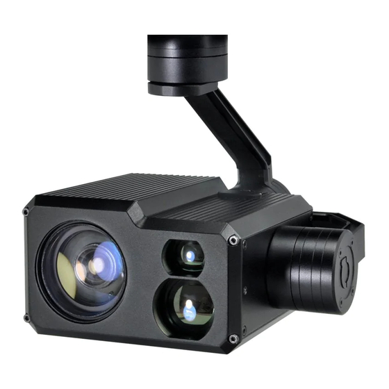
Important Note 1.Product Introduction 1.1 Introduction Z30TM is a powerful 3-axis gimbal integrated with a 30x optical zoom SONY camera and a 1.5km laser rangefinder. It supports visible optical zoom, photographing and video, target tracking and laser distance measuring. OSD can display angle, zoom times, status of record and picture mode, tracking frame, also can select to turn off the OSD. -
Page 3: Standard Version
Z30TM is widely used in UAV industries of public security, electric power, fire fighting, zoom aerial photography and other industrial applications. 1.2 In the Box A. Standard Version Gimbal Camera USB to TTL Cable x 1 pc x 1 pc... -
Page 4: Installation Instruction
TTL / S.BUS Control Cable x 1 pc TTL Connect Cable x 3 pcs Ethernet Cable x 1 pc 2. Installation Instruction 2.1 Overview [11] [13] [12] Control Box Back Side [10] (Standard Version) [11] [14] [13] Viewport [12] (Viewport Version) - Page 5 [8] TF card slot [1] Control box [2] Upper damping board [9] Roll axis motor [3] Lower damping board [10] Pitch axis motor [4] laser rangefinder [11] 3-6S power interface [5] FHD zoom camera [12] Micro HDMI interface [6] Damping ball [13] Ethernet interface [7] Yaw axis motor [14] Viewport unlock button...
- Page 6 2.2.2 Control Box Printing (Viewport Version) Front Side POWER Left Side ETHERNET UART & S.BUS Right Side...
- Page 7 2.3 Device Dimensions (Standard Version) Unit: mm 69.9 45.0 60.0 69.7 51.4 13.5 137.8 145.7...
- Page 8 2.3 Device Dimensions (Viewport Version) Unit: mm 78.0 Control Box 91.0 91.0 φ23 91.0 60.0 25.5 30.4 137.8 145.7...
- Page 9 2.4 Install Mounting Part (1) Find out the arrow on the gimbal which indicating the yaw heading of the payload (i.e. the lens direction when the camera power on), and synchronize with the direction specified by the UAV. (2) Fix one end of the copper cylinder on the screw hole of lower damping board, and use M3 screw to fasten it.
- Page 10 2.5 Viewport Release Instruction × 1. Make sure the two white stripes indicated in above picture are aligned with each other. (If the stripes are not aligned to each other, please pinch the connector part and turn it to left manually)
- Page 11 2. Align the white dot (unlock icon) to the red triangle (below unlock button), push the gimbal into the Viewport completely and then rotate the gimbal camera anticlockwise. 3. When you hear "click" sound (when red dot is aligned to the red triangle) means the gimbal camera and Viewport has been locked.
- Page 12 2.6 Install TF Card TF (Micro SD card): Install the TF card to the card slot (Re. 2.1 Overview). Support max 128GB. Request Class 10 (10m/s) transmis- sion speed or higher and FAT32 or exFAT format. Make sure device is power off when inserting the TF card, hot plugging is not supported.
-
Page 13: Signal Control
Above output mode is optional. Please subject to your actual product. When using user interface software Viewlink for network connection, the network of external device (computer) should be the IP address: 192.168.2.2 (choose the last byte among 2~254, can not be 119 same as the gimbal), subnet mask: 255.255.255.0, Default gateway: 192.168.2.1, and all firewalls of the computer must be closed. - Page 14 PWM IN 5V OUTPUT Remote Controller Receiver Connection Diagram (Standard Version) Receiver Remote Controller Connection Diagram (Viewport Version)
- Page 15 3.1.2 PWM Control Operation Instruction 1) Pitch (PWM Pitch channel in to control Pitch. Joystick, rotary knob or 3-gear switch on remote control are optional. 3-gear switch as example.) Position 1 Position 2 Position 3 Low Gear Middle Gear High Gear Pitch Up Pitch Stop Pitch Down...
- Page 16 Position 1 Position 2 Position 3 Low Gear Middle Gear High Gear Position 1: Low speed mode, control pitch / yaw with this mode at lowest speed Position 2: Middle speed mode, control pitch / yaw with this mode at middle speed Position 3: High speed mode, control pitch / yaw with this mode at highest speed...
- Page 17 4) Zoom (PWM Zoom channel in to control Zoom. Joystick, rotary knob or 3-gear switch on remote control are optional. 3-gear switch as example.) Position 1 Position 2 Position 3 Low Gear Middle Gear High Gear Zoom Out Stop Zoom Zoom In 5) Focus (not functional for this channel) 6) Pic/Rec (PWM Pic/Rec channel in to control take picture and...
- Page 18 7) Multi: tracking control Position 1 Position 2 Position 3 Low Gear Middle Gear High Gear Switch from Position 2 to 1: Cancel tracking Switch from Position 2 to 3: Exit the tracking, display the lock frame in the center of the screen, start tracking Switch from Position 3 to 2: "+"...
- Page 19 USB to TTL Cable Control Box Connection Diagram Standard Version USB to TTL Cable Viewport Control Box Connection Diagram Viewport Version Diagram of USB to TTL Cable: Connect the camera to the upper computer by USB to TTL cable (Adopt connection method of TX to RX, RX to TX, GNG to GND at Dupont ends of the provided USB to TTL cable, connect to the specified TTL of the gimbal, and the USB end of the cable connect to computer).
-
Page 20: S.bus Control
ViewLink is a user interface developed by Viewpro for Viewpro gimbal cameras, you can download it from Viewpro website (www.viewpro- tech.com) or ask distributors for installation package. Connect serial port of gimbal to pins, DO NOT connect with power supply. - Page 21 Receiver Remote Control Wiring Diagram Viewport Version S.Bus control mode: default S.Bus signal channel 9-15 to control gimbal camera functions (the function of channel is consistent with corresponding channel in PWM function description) Channel 9: Yaw Control Channel 10: Pitch Control Channel 11: Mode Control Channel 12: Zoom Control Channel 13: Focus Control...
-
Page 22: Specification
(please contact with our technical support for the setting instruction.) 3.4 TCP control For Viewpro gimbal cameras with Ethernet output, the default IP address is: 192.168.2.119, control port: 2000. You can send the corresponding protocol to realize TCP control after connecting. - Page 23 Output voltage 5V (connect with PWM) Dynamic current 450mA @ 12V Idle current 330mA @ 12V Power consumption ≤ 5.4W Working environment '-20℃ ~ +80℃ temp micro HDMI(HD output 1080P 60fps) / Output Network interface / SDI SD card (Up to 128G, class 10, FAT32 or ex Local-storage FAT format) Control method...
- Page 24 Effective pixel 2.13MP Lens optical zoom 30x, F=4.3~129mm Digital zoom 12x (360x with optical zoom) 10mm(wide end) to 1200mm(tele end). Min object distance Default 300mm 1080p mode: 63.7°(wide end) ~ 2.3°(tele end) Horizontal viewing 720p mode: 63.7°(wide end) ~ 2.3°(tele end) angle SD: 47.8°(wide end) ~ 1.7°(tele end) Sync system...
- Page 25 Defog Camera Object Tracking Update rate of 50Hz deviation pixel Output delay of <10ms deviation pixel Minimum object contrast Minimum object size 16*16 pixel Maximum object size 160*160 pixel Tracking speed 32 pixel/frame Object memory time 100 frames (4s) The mean square root values of pulse <...
- Page 26 2. Does Z30TM support taking photos during recording? A: Yes 3. How to set the storage format of Z30TM ? A: When the IP output resolution is set to 1280*720, the storage resolution is 1920 * 1080; Storage resolution is 1280 * 720 when the IP output resolution is set to 1920*1080;...
Need help?
Do you have a question about the Z30TM and is the answer not in the manual?
Questions and answers