Table of Contents
Advertisement
Quick Links
Advertisement
Table of Contents

Related Manuals for sauermann Si-CA 130


Summary of Contents for sauermann Si-CA 130
- Page 1 USER MANUAL Si-CA 130 GAS ANALYZER www.sauermanngroup.com...
-
Page 2: Table Of Contents
Table of contents 1. Safety instructions ..............................5 1.1 Warnings ................................5 1.2 Environment protection ............................ 5 1.3 Symbols used ..............................5 2. Introduction ................................6 2.1 Analyzer description ............................6 2.2 Main features ..............................7 3. First Start-up ................................ 10 4. -
Page 3: Safety Instructions
Send back the device at its end of working life to a waste collection center for electrical and electronic components (ac- cording to local regulations), or send it back to Sauermann to ensure a required waste collection in the respect of the environment. -
Page 4: Introduction
Color touch screen, 10.9 cm (4.3’’), 480 x 272 pixels with backlight. It allows to display measured parameters in a more The Si-CA 130 is a flue gas analyzer for emissions monitoring of boiler, engine, & other combustion applications with comfortable format for the operator. - Page 5 • Smoke/Soot: Smoke index value tion, BS 7967:2015, BS EN 50543:2011, UNE 60670-10 and ES.02173.ES Hereby, Sauermann Industrie SAS declares that the radio equipment type Si-CA 130 is in compliance with Directive • Atmospheric Pressure: Input for Atmospheric Pressure 2014/53/EU. The full text of the EU declaration of conformity is available at the following internet address: www.sauermanngroup.com...
-
Page 6: First Start-Up
3. First Start-up 4. Features 4.1 General features When the analyzer is first started up, parameters of the analyzer must be set. Dimensions 19.4 x 9.9 x 4.9 cm (7.5 x 3.5 x 4.9’’) Keep pressed for 3 seconds to turn ON the analyzer. Weight 350 g (12 oz) DO NOT insert the gas probe in the flue/chimney/stack at this time. -
Page 7: Parameter Specifications
0 to 7500 ppm 1 ppm In case of any default or damage of the instrument, Sauermann After-sales service shall be contacted. On the back of the analyzer, there is a label with the analyzer serial number. This Low NOx... -
Page 8: Perform A Draft Measurement With The Draft Probe
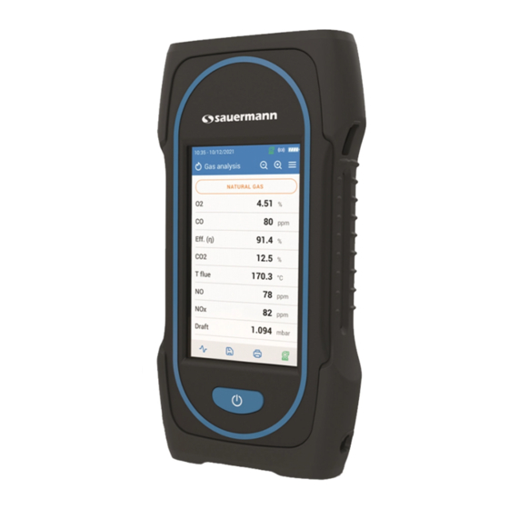
5.3.2 Perform a draft measurement with the draft probe 5.8 Use the Zoom function The draft measurment can be performed thanks to the draft probe avalaible as option. From the gas analysis screen, the zoom function is available using The initial screen displays 8 measured values. If the draft probe is used, it will be necessary to drill another hole dedicated to this draft meas- urement in the duct. -
Page 9: Set The General Parameters Of The Analyzer
6. Set the general parameters of the analyzer 6.8 Set the brightness of the screen “Settings > General” screen is displayed. The settings menu allows to set the general parameters of the analyzer: • Tap “Brightness”. • Time • Set the brightness level from 1 to 5. •... -
Page 10: Set The Parameters Of The Analysis
This part allows to select the required fuels for the gas analysis but it also allows to add customized fuels. If a very specific fuel must be created please contact the Sauermann Service Center for further information. 7.1.1 Select the fuel A customized fuel can be deleted: The default list of fuels is dependent on the country selected. -
Page 11: Set The Nox Factor
7.3 Set the NOx factor • Return to main Alarm screen and tap on the activate button in order for the alarm to be enabled. • Repeat the procedure for other alarms as needed. This part allows to set the NOx factor, which is the assumed NO to NO ratio used to calculate NOx when the NO sensor is included but the NO is not included. -
Page 12: Set The Atmospheric Pressure
7.7 Set the atmospheric pressure 7.9 Set the display configuration This part allows to set the atmospheric pressure in which measurements are performed. This value is taken into account This section is used to organize the display of values on the gas analysis screen. in calculations such as the smoke velocity. -
Page 13: Set The Measuring Unit
8. Set the measuring unit 9. Set the data saving This part allows to define the measuring unit for each parameters measured or calculated by the analyzer. This part allows to define the data saving mode: manual or data logger The following unit is avalaible according to the parameter: “Settings”... -
Page 14: Set The Printer
11.1.2 Service center contact “Service / Calibration” screen is displayed. • Tap “Service Center Contact” to display the address of the Sauermann Service Center. 11.1.3 Perform calibration This screen allows the user to perform a calibration on a gas sensor. -
Page 15: Gas Sensor Information
• Sensor life estimation: a four bar display is shown. When down to one bar, it is recommended to contact an authorized • Tap “Start stabilization”. Sauermann service center The analyzer starts the stabilization which takes 15 minutes. At the end of the stabilization, the analyzer starts the test and then displays the following results: 11.3 Other information... -
Page 16: Gas Pump Flow Rate
12.3 Gas pump flow rate If Preliminary test is selected: • Select the fuel: natural gas or LPG. This screen shows the real-time measured flow rate of the gas passing through the analyzer as performed by the main • Read the gas pressure inside the pipe. flue gas sampling pump. -
Page 17: Perform A Measurement Of Smoke/Opacity
• Put a new sensor respecting the way of sensor for NO sensor as shown on picture 6. • Replace the black manifold on the Si-CA 130 electronic board making sure to properly align the 10 metal pins (4) into the mating black connector (7). -
Page 18: Replace Filter Inside The Water Trap
14. Optional accessories Sensors have very precise locations, see the following locations defined for each sensor: The following accessories are available: Part number Description Illustration 27520 (NO) NO or Low NO sensor for NOx 27521 (Low NO) • O2 sensor must be in O position •... -
Page 19: Spare Parts
Sauermann NA C/Albert Einstein 33. 140 Fell Court, Ste. 302 27713 Cell cap for SI-CA 130, to cover third sensor location when not used with gas sensor Planta 3. P. I. Santa Margarida II- Hauppauge, New York 11788 08223 Terrassa (Spain)
Need help?
Do you have a question about the Si-CA 130 and is the answer not in the manual?
Questions and answers