Table of Contents
Advertisement
Quick Links
Advertisement
Table of Contents

Related Manuals for sauermann Si-CA 030


Summary of Contents for sauermann Si-CA 030
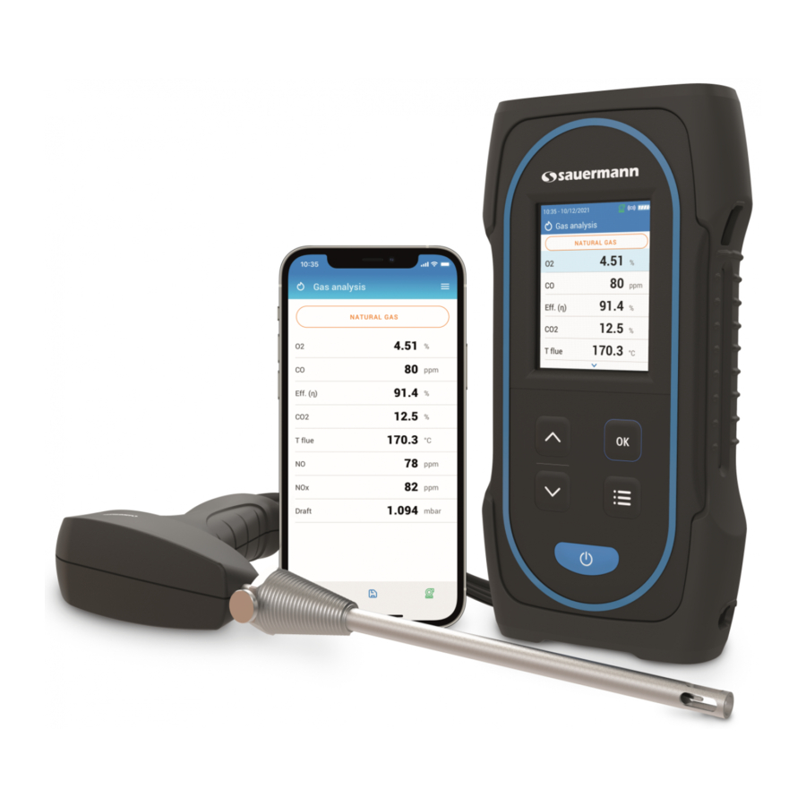
- Page 1 USER MANUAL Si-CA 030 GAS ANALYZER www.sauermanngroup.com...
-
Page 2: Table Of Contents
Table of contents 1. Safety instructions ..............................5 1.1 Warnings ................................5 1.2 Environment protection ............................ 5 1.3 Symbols used ..............................5 2. Introduction ................................6 2.1 Analyzer description ............................6 2.2 Main features ..............................7 3. First Start-up ................................9 4. -
Page 3: Safety Instructions
Send back the device at its end of working life to a waste collection center for electrical and electronic components (ac- cording to local regulations), or send it back to Sauermann to ensure a required waste collection in the respect of the environment. -
Page 4: Introduction
Color screen, 7.1 cm (2.8''), 320 x 240 pixels with backlight. It allows to display measured parameters in a more comfort- The Si-CA 030 is a flue gas analyzer for emissions monitoring of boiler, engine, & other combustion applications with two able format for the operator. -
Page 5: First Start-Up
EN 50379-1 and EN 50379-2, UNI 10389, UL & cUL Certification, BS 7967:2015, BS EN 50543:2011, UNE 60670-10 and ES.02173.ES. Hereby, Sauermann Industrie SAS declares that the radio equipment type Si-CA 030 is in compliance with Directive 2014/53/EU. The full text of the EU declaration of conformity is available at the following internet address: DO NOT insert the gas probe in the flue/chimney/stack. -
Page 6: Features
4. Features 4.3 Parameter specifications Parameter Sensor Measuring range Resolution Accuracy R e s p o n s e 4.1 General features time Electroche- 0 to 25% 0.01% ±0.2% vol < 30 s mical Dimensions 19.4 x 9.9 x 4.9 cm (7.5 x 3.5 x 4.9’’) ±8 ppm <... -
Page 7: Perform A Flue Gas Analysis
During the combustion gas analysis, when measurements are constant, it is possible to save the gas analysis data to a previously created data folder or to a newly created folder. To save data, use the Sauermann Combustion app. • Press Menu icon 5.5 Print the analysis results... -
Page 8: Set The General Parameters Of The Analyzer
6. Set the general parameters of the analyzer 6.7 Set the purge time This part allows to set the purge time duration. The Settings menu allows to set the general parameters of the analyzer: “Settings > General” screen is displayed. •... -
Page 9: Set The Parameters Of The Analysis
The customized fuel is then integrated at the end of the fuel list. • Zero draft sensor • Atmospheric pressure If a very specific fuel must be created, please contact the Sauermann Service Center for further information. • Air temperature • Display configuration A customized fuel can be deleted: •... -
Page 10: Set The Nox Factor
7.4 Set the NOx factor This part allows to set the NOx factor, which is the assumed NO to NO ratio used to calculate NOx. “Settings > Analysis” screen is displayed. • Go to “NOx factor”and press OK. • Use arrow and OK keys to enter the required NOx factor in percentage between 1.00 and 1.50. •... -
Page 11: Set The Display Configuration
8. Set the measuring unit • Use arrow and keys to enter the required air temperature. • Press Menu button to save value and exit screen exit. This part allows to define the measuring unit for each parameter measured or calculated by the analyzer. The following unit is avalaible according to the parameter: If the external probe or the internal sensor senor is used, just activate the air temperature. -
Page 12: Set The Printer
• Use up and down arrows to define the number of copies. Maximum number of copies is five. “Service / Calibration” screen is displayed. • Press Menu button to save selection and exit screen. • Go to “Service Center Contact” and press OK to display the contact information of the Sauermann Service Center. 10.1.3 Perform calibration This screen allows the user to perform a calibration on a gas sensor. - Page 13 11. Perform other measurements • Date of last calibration • Date of installation The analyzer can perform other measurements than a gas analysis: • Output current (in units of micro amps) • CO monitor • Sensor life estimation • Gas/pump flow rate 10.3 Other information •...
- Page 14 • CO sensor must be in CO position to replace it. To ensure the measurement accuracy, sensors have to be calibrated only in Assistance center qualified by • NO sensor must be in NO position Sauermann. Sensor Average life-time Required calibration...
- Page 15 Part number Description Illustration Item number Description 27695 Upper Shell Assembly for Si-CA 030, with protective glass, keyboard and normative label 27696 Lower Shell Assembly for Si-CA 030, with magnets 27521 NO sensor for NOx 27697 Bottom Shell Piece with Hose & Tc Connection Ports...
- Page 16 Sauermann Industrie Sauermann Italia SA ZA Bernard Moulinet Via Golini 61/10 24700 Montpon 40024 Castel S.Pietro Terme (BO) France T. (+39)-051-6951033 T. +33 (0)5 53 80 85 00 F. (+39)-051-942254 services@sauermanngroup.com info.italy@sauermanngroup.com Sauermann Ibérica Sauermann NA C/Albert Einstein 33. 140 Fell Court, Ste. 302 Planta 3.
Need help?
Do you have a question about the Si-CA 030 and is the answer not in the manual?
Questions and answers