Table of Contents
Advertisement
Quick Links
Advertisement
Table of Contents

Related Manuals for Asus R680EI-IM-A


Summary of Contents for Asus R680EI-IM-A
- Page 1 R680EI-IM-A...
- Page 2 Product warranty or service will not be extended if: (1) the product is repaired, modified or altered, unless such repair, modification of alteration is authorized in writing by ASUS; or (2) the serial number of the product is defaced or missing.
-
Page 3: Table Of Contents
Contents Chapter 1 Product overview Package contents ................. 1-1 Features ..................1-1 1.3 Specifications ................1-2 Chapter 2 Motherboard information Before you proceed ..............2-1 Motherboard layout ..............2-2 Central Processing Unit (CPU) ........... 2-4 2.3.1 CPU installation .............. 2-5 2.3.2 CPU heatsink and fan assembly installation .... - Page 4 3.3.13 Network Stack Configuration ........3-11 3.3.14 USB Configuration ............3-12 3.3.15 NVMe Configuration ............3-12 3.3.16 Onboard Devices Configuration ........3-13 3.3.17 Miscellaneous ............... 3-13 3.3.18 APM Configuration ............3-13 3.3.19 EZ-Flash ............... 3-15 3.3.20 IO Expander Configuration ........... 3-15 3.3.21 Watchdog Timer ............
-
Page 5: Chapter 1 Product Overview
Chapter 1 Product overview Package contents Check your industrial motherboard package for the following items. 1 x ASUS R680EI-IM-A Motherboard 1 x Serial ATA 6.0 Gb/s cable 1 x M.2 screw package 1 x ASUS I/O Shield NOTE: If any of the above items is damaged or missing, contact your distributor or sales representative immediately. -
Page 6: Specifications
1 x USB 3.2 Gen 1 port 4 x USB 2.0 ports Rear panel I/O ports 2 x LAN (RJ45) ports 1 x P/S2 keyboard port 1 x P/S2 mouse port 1 x COM port (RS232/422/485) 2 x Audio jacks (continued on the next page) R680EI-IM-A... - Page 7 RedHat Enterprise Fedora Workstation OpenSUSE Certification CE, FCC Form Factor Mini-ITX Form Factor, 6.7”x 6.7” (17.0cm x 17.0cm) NOTE: Specifications are subject to change without notice. Please refer to the ASUS website for the latest specifications. Chapter 1: General information...
- Page 8 R680EI-IM-A...
-
Page 9: Chapter 2 Motherboard Information
Chapter 2 Motherboard information Before you proceed Take note of the following precautions before you install motherboard components or change any motherboard settings. CAUTION! • Unplug the power cord from the wall socket before touching any component. • Before handling components, use a grounded wrist strap or touch a safely grounded object or a metal object, such as the power supply case, to avoid damaging them due to static electricity. -
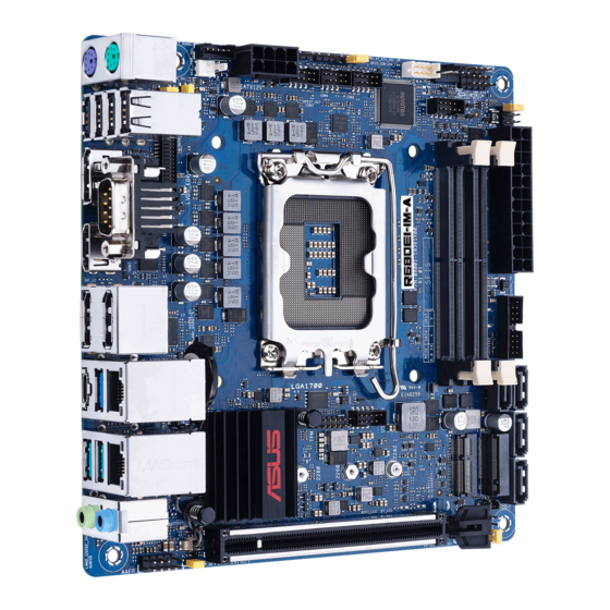
Page 10: Motherboard Layout
USB_9~12 COM1 HDMI Place this side towards the rear LGA1700 DP_12 of the chassis Intel ® i210AT LAN1_U32G1_5 U32G2_C1 128Mb BIOS USB_213 U32G1_6 LAN1_U32G2_45 Intel ® R680E Intel ® I225LM 2280 2260 2242 AUDIO CLRTC COM_DEBUG PCIEX16(G5) DIS_ME COM1_SEL R680EI-IM-A... - Page 11 Page Connectors/Jumpers/Slots CPU and Chassis Fan headers (4-pin CPU_FAN, 4-pin CHA_FAN) 2-18 Display panel VCC power selection (6-pin VCC_PWR_SEL) 2-10 LVDS/eDP Backlight panel connector (5-pin LCD_BLKT_PANEL) 2-22 ATX Power connectors (24-pin EATXPWR, 8-pin EATX12V) 2-24 Intel LGA1700 CPU socket ® Digital Audio header (4-1 pin SPDIF_OUT) 2-23 Chassis Intrude header (4-1 pin CHASSIS)
-
Page 12: Central Processing Unit (Cpu)
Return Merchandise Authorization (RMA) requests only if the motherboard comes with the cap on the LGA1200 socket. • The product warranty does not cover damage to the socket contacts resulting from incorrect CPU installation/removal, or misplacement/loss/ incorrect removal of the PnP cap. R680EI-IM-A... -
Page 13: Cpu Installation
2.3.1 CPU installation Chapter 2: Motherboard information... - Page 14 R680EI-IM-A...
-
Page 15: Cpu Heatsink And Fan Assembly Installation
2.3.2 CPU heatsink and fan assembly installation CAUTION! Apply the Thermal Interface Material to the CPU heatsink and CPU before you install the heatsink and fan if necessary. To install the CPU heatsink and fan assembly LGA1200 LGA1700 LGA1800 Chapter 2: Motherboard information... - Page 16 To uninstall the CPU heatsink and fan assembly R680EI-IM-A...
-
Page 17: System Memory
System memory This motherboard comes with two Double Data Rate 5 (DDR5) Small Outline Dual Inline Memory Module (SO-DIMM) sockets. The figure below illustrates the location of the DDR5 SO-DIMM sockets: Channel Sockets Channel A SO-DIMM_B1 Channel B SO-DIMM_A1 Recommended memory configuration DIMM_A1 DIMM_B1 DIMM_A1... -
Page 18: Jumpers
(Default) Setting Pins 3V (Default) Connector type HEADER 2 x 3p, 2.54mm pitch, S/T COM1/2 Ring/+5V/+12V selection (6-pin COM1_SEL, COM2_SEL) COM2_SEL +12V (Default) COM1_SEL +12V (Default) Setting Pins +12V Ring (Default) Connector type HEADER 2x3p, 2.54mm pitch, S/T R680EI-IM-A 2-10... - Page 19 AT/ATX mode selection (3-pin AT_ATX_SEL) AT_ATX_SEL ATX mode AT mode (Default) Pins 1-2 (Default) ATX mode AT mode Connector type HEADER 1x3p, 2.54mm pitch, S/T Disable ME jumper (3-pin DIS_ME) This jumper allows you to enable or disable the Intel ME function.
- Page 20 CHASSIS PIN 1 Connector type HEADER 4p, K2, 2.54mm pitch LVDS/eDP Panel Enable Signal Selection header (BKLTEN_SEL) BKLTEN_SEL High Active Low Active (Default) Pins 1-2 (Default) High Active Low Active Connector type HEADER 1x3p, 2.54mm pitch, S/T R680EI-IM-A 2-12...
- Page 21 Clear CMOS header (2-pin CLRTC) This header allows you to clear the CMOS RTC RAM data of the system setup information such as date, time, and system passwords. CLRTC PIN 1 Connector type HEADER 1x2p, 1.25mm pitch, S/T To erase the RTC RAM: Turn OFF the computer and unplug the power cord.
-
Page 22: Connectors
Activity/Link LED Speed LED ACT/LINK SPEED Status Description Status Description No link 10Mbps/100Mbps connection Green Linked ORANGE 1Gbps connection Green (Blinking) Data activity GREEN 2.5Gbps connection LAN port Green (Blinking then Ready to wake up steady) from S5 mode R680EI-IM-A 2-14... - Page 23 Line In port (light blue). This port connects to the tape, CD, DVD player, or other audio sources. PS/2 keyboard port (purple). This port is for a PS/2 keyboard. port. HDMI These ports are for a High-Definition Multimedia Interface (HDMI ®...
-
Page 24: Internal Connectors
3.2 Gen 1 specifications and provide faster data transfer speeds of up to 5 Gbps, faster charging time for USB-chargeable devices, optimized power efficiency, and backward compatibility with USB 2.0. U32G1_6 U32G1_78 PIN 1 USB3+5V USB3+5V IntA_P1_SSRX- IntA_P2_SSRX- IntA_P1_SSRX+ IntA_P2_SSRX+ IntA_P1_SSTX- IntA_P2_SSTX- IntA_P1_SSTX+ IntA_P2_SSTX+ IntA_P1_D- IntA_P2_D- IntA_P1_D+ IntA_P2_D+ R680EI-IM-A 2-16... - Page 25 USB 2.0 header (10-1 pin USB213) This header is for an USB 2.0 port. Connect the USB cable to this header. This USB header complies with USB 2.0 specification that supports up to 480 Mbps connection speed. USB_213 PIN 1 Connector type Header 2x5p, K9, 2.0mm pitch CAUTION! Never connect a 1394 cable to the USB connector.
- Page 26 This header supports a Trusted Platform Module (TPM) system with a Serial Peripheral Interface (SPI), allowing you to securely store keys, digital certificates, passwords and data. A TPM system also enhances network security, protects digital identities, and ensures platform integrity. Connector type Header 2x7p, K14, 2.0mm pitch R680EI-IM-A 2-18...
- Page 27 Front Panel System Panel header (10-1 pin F_PANEL) This header supports several chassis-mounted functions. +PWR_LED PWR_BTN F_PANEL PIN 1 +HDD_LED RESET Connector type Header 2x5p, K10, 2.54mm pitch • System power LED (2-pin +PWR_LED) This 2-pin header is for the system power LED. Connect the chassis power LED cable to this connector.
- Page 28 WAFER HD 2x20p, 1.25mm pitch 10. Speaker header (4-pin SPEAKER) The 4-pin header is for the chassis-mounted system warning speaker. The speaker allows you to hear system beeps and warnings. SPEAKER PIN 1 Connector type HEADER 1x4p, 2.54mm pitch, S/T R680EI-IM-A 2-20...
- Page 29 11. RTC Battery header (2-pin BATTERY) This header is for the lithium CMOS battery. BATTERY PIN 1 12. M.2 socket 3 This socket allows you to install an M.2 SSD module. M.2(SOCKET3) NOTES: • The M.2 SSD module is purchased separately. •...
- Page 30 NOTE: The serial port cables are purchased separately. 15. Flat panel display brightness connector (5-pin LCD_BLKT_PANEL) This connector is for the LVDS/eDP panel backlight voltage selection. LCD_BLKT_PANEL LVDS Signal eDP Signal PIN1 PIN1 Connector type WAFER 6p, 2.0mm pitch R680EI-IM-A 2-22...
- Page 31 Digital Audio header (4-1 pin SPDIF_OUT) This header is for an additional Sony/Philips Digital Interface (S/PDIF) port. Connect the S/PDIF Out module cable to this header, then install the module to a slot opening at the back of the system chassis. SPDIF_OUT PIN 1 Connector type...
- Page 32 +3.3V out +3.3V out +5V out PSON# +5V out +12V out +5V out +12V in +5V out +12V in +5V out +3.3V out DC Mode EATX12V Pins Signal Pins Signal +12V in +12V in +12V in +12V in R680EI-IM-A 2-24...
-
Page 33: Slot
Slot PCI Express slot This slot supports a PCIe 5.0 x16 graphics card that complies with the PCI Express specification. PCIEX16(G5) Chapter 2: Motherboard information 2-25... - Page 34 R680EI-IM-A 2-26...
-
Page 35: Chapter 3 Bios Setup
Always shut down the system properly from the operating system. IMPORTANT! • Visit the ASUS website at www.asus.com to download the latest BIOS file for this motherboard. • The default BIOS settings for this motherboard apply to most working conditions and ensures optimal performance. -
Page 36: Main Menu
Configuration options: [Disable Link] [Enabled] The following item appears when you set Switch to LVDS to [Enabled]. All-in-One Chassis Allows you to select All-in-One (AiO) Chassis (if applicable) for simplified AiO configuration. Configuration options: [None] [1920*1080 LVDS1] [1920*1080 LVDS2] [1920*1080 LVDS3] [1600*900 LVDS4] R680EI-IM-A... - Page 37 • Be cautious when selecting AiO chassis. Incorrect selection of AiO chassis can cause incorrect operation or potential damage to AiO chassis hardware. • The following items appear only when you set All-in-One Chassis to [None]. EDID Data Source Configuration options: [Pre-Defined] [Flat Panel Display] The following item appears when you set EDID Data Source to [Pre-Defined].
-
Page 38: Pch-Fw Configuration
Allows you to select to tell O.S. to support PPI Spec Version 1.2 or 1.3. Configuration options: [1.2] [1.3] Some HCK tests might not support 1.3. PH Randomization Allows you to enable or disables Platform Hierarchy randomization. Configuration options: [Disabled] [Enabled] R680EI-IM-A... -
Page 39: Cpu Configuration
Do not enable this question in production platforms. This is for development testing. OVERRIDE ChangePlatformAuth ELINK for production platforms supports TXT. 3.3.4 CPU Configuration The items in this menu show CPU-related information the BIOS automatically detects. Intel (VMX) Virtualization Technology This item, when set to [enabled], will allow a VMM to utilize the additional hardware capacities provided by Vanderpool Technology. -
Page 40: Graphics Configuration
This item allows you to configure system ACPI parameters. Enable ACPI Auto Configuration Allows you to enable or disable BIOS ACPI Auto Configuation. Configuration options: [Disabled] [Enabled] Enable Hibernation Enables or disables system ability to Hibernate (0S/S4 Sleep State). Configuration options: [Disabled] [Enabled] R680EI-IM-A... -
Page 41: Pci Express Configuration
ACPI Sleep State Allows you to select the highest ACPI sleep state the system will enter when the SUSPEND button is pressed. Configuration options: [S3 (Suspend to RAM)] [Suspend Disabled] 3.3.7 PCI Express Configuration This item allows you to configure PCI Express settings. PCIEX16 Slot Allows you to configure the PCI Express Root Port settings. -
Page 42: Super Io Configuration
Allows you to enable or disable the serial port (COM).Configuration options: [Disabled] [Enabled] Serial Port 4 Configuration This item allows you to set parameters of Serial Port 4 (COMD). Serial Port Allows you to enable or disable the serial port (COM).Configuration options: [Disabled] [Enabled] Serial Port 5 Configuration R680EI-IM-A... -
Page 43: Serial Console Redirection
This item allows you to set parameters of Serial Port 5 (COME). Serial Port Allows you to enable or disable the serial port (COM).Configuration options: [Disabled] [Enabled] 3.3.10 Serial Console Redirection COM1(~5) Console Redirection Allows you enable or disable the console redirection feature. Configuration options: [Enabled] [Disabled] The following item is accessible when you set Console Redirection to [Enabled]. - Page 44 This allows you to set the number of rows and columns supported on the Legacy OS. Configuration options: [80x24] [80x25] Redirect After POST Configuration options: [Always Enable] [BootLoader] [Always Enable] Legacy Console Redirection is enabled for Legacy OS. [BootLoader] Legacy Console Redirection is disabled before booting to Legacy OS. R680EI-IM-A 3-10...
-
Page 45: Sata Configuration
3.3.11 SATA Configuration This item allows you to configure SATA device options settings. SATA Controller(s) Allows you to enables or disables the onboard SATA device. Configuration options: [Disabled] [Enabled] The following item appears only when you set SATA Controller(s) to [Enabled]. SATA Mode Selection Allows you to determine how SATA controller(s) operate. -
Page 46: Usb Configuration
BIOS or OS. Configuration options: [Disabled] [Enabled] 3.3.15 NVMe Configuration The NVMe Configuration menu displays the NVMe controller and drive information of the devices connected and allows you to configure NVMe device options settings. R680EI-IM-A 3-12... -
Page 47: Onboard Devices Configuration
3.3.16 Onboard Devices Configuration HD Audio Controller Allows you to control detection of the HD-Audio device. Configuration options: [Enabled] [Disabled] [Enabled] Enables the HD Audio Device unconditionally. [Disabled] Disables the HD Audio Device unconditionally. LAN1 I225 Configuration options: [Disabled] [Enabled] LAN2 I210 Configuration options: [Disabled] [Enabled] M.2 WiFi Allows you to enable or disable M.2 WiFi. - Page 48 Allows you to enter a natural number within 0-23 for hour. For example, enter 3 for 3:00 am and 15 for 3:00 pm. Wake up minute Allows you to enter a natural number within 0-59 for minute. Wake up second Allows you to enter a natural number within 0-59 for second. R680EI-IM-A 3-14...
-
Page 49: Ez-Flash
The following items appear when you set Power On By RTC to [Monthly event]. Day of the Month Allows you to select the day of the month when the system is to wake up. Wake up hour Allows you to enter a natural number within 0-23 for hour. For example, enter 3 for 3:00 am and 15 for 3:00 pm. -
Page 50: Hardware Monitor Menu
1. Select the Administrator Password item and press <Enter>. 2. From the Enter Current Password box, key in the current password, then press <Enter>. 3. From the Create New Password box, key in a new password, then press <Enter>. 4. Confirm the password when prompted. R680EI-IM-A 3-16... -
Page 51: User Password
To clear the administrator password, follow the same steps as in changing an administrator password, but press <Enter> when prompted to create/confirm the password. 3.5.2 User Password If you have set a user password, you must enter the user password for accessing the system. -
Page 52: Boot Menu
Allows you to exit the system setup program without saving the changes you made. When you select this option or if you press <Esc>, a confirmation window appears. Select Yes to discard changes and exit. Save Changes and Reset Allows you to reset the system setup after saving the changes. R680EI-IM-A 3-18... - Page 53 Discard Changes and Reset Allows you to reset the system setup without saving the changes you made. Save Options Save Changes Allows you to save changes done so far to any of the setup options. Discard Changes Allows you to discard changes done so far to any of the setup options. Restore Defaults Allows you to restore or load default values for all the setup options.
-
Page 54: Appendix
Appendix Notices FCC Compliance Information Responsible Party: Asus Computer International Address: 48720 Kato Rd., Fremont, CA 94538, USA Phone / Fax No: (510)739-3777 / (510)608-4555 This device complies with part 15 of the FCC Rules. Operation is subject to the following two conditions: (1) This device may not cause harmful interference, and (2) this device must accept any interference received, including interference that may cause undesired operation. - Page 55 : (1) l’appareil ne doit pas produire de brouillage, et (2) l’utilisateur de l’appareil doit accepter tout brouillage radioélectrique subi, même si le brouillage est susceptible d’en compromettre le fonctionnement. CAN ICES-003(B)/NMB-003(B) VCCI: Japan Compliance Statement Class B ITE KC: Korea Warning Statement R680EI-IM-A...
- Page 56 ASUS Recycling/Takeback Services ASUS recycling and takeback programs come from our commitment to the highest standards for protecting our environment. We believe in providing solutions for you to be able to responsibly recycle our products, batteries, other components as well as the packaging materials.
- Page 57 доступний на: www.asus.com/support Cijeli tekst EU izjave o sukladnosti dostupan je na: www.asus.com/support Türkçe AsusTek Computer Inc., bu aygıtın temel gereksinimlerle ve ilişkili Čeština Společnost ASUSTeK Computer Inc. tímto prohlašuje, že toto Yönergelerin diğer ilgili koşullarıyla uyumlu olduğunu beyan eder.
-
Page 58: Service And Support
Service and Support Visit our multi-language website at https://www.asus.com/support/ Manufacturer ASUSTek COMPUTER INC. Address, City 1F., No. 15, Lide Rd., Beitou Dist., Taipei City 112, Taiwan Authorized Representative ASUS COMPUTER GmbH in Europe Address Harkortstrasse 21-23, 40880 Ratingen Country Germany...
Need help?
Do you have a question about the R680EI-IM-A and is the answer not in the manual?
Questions and answers