Table of Contents
Advertisement
Quick Links
Advertisement
Table of Contents

Related Manuals for Asus Rog Zenith II Extreme


Summary of Contents for Asus Rog Zenith II Extreme
- Page 1 ZENITH II EXTREME...
- Page 2 Product warranty or service will not be extended if: (1) the product is repaired, modified or altered, unless such repair, modification of alteration is authorized in writing by ASUS; or (2) the serial number of the product is defaced or missing.
-
Page 3: Table Of Contents
Contents Safety information ...................... vi About this guide ......................vii ROG ZENITH II EXTREME specifications summary ..........ix Package contents ..................... xiv Installation tools and components ................xv Chapter 1: Product Introduction Before you proceed ................... 1-1 Motherboard layout..................1-2 Central Processing Unit (CPU) .............. - Page 4 3.6.9 USB Configuration ..............3-18 Monitor menu ................... 3-19 Boot menu ....................3-19 Tool menu ....................3-21 3.9.1 ASUS EZ Flash 3 Utility ............3-21 3.9.2 Secure Erase ................3-22 3.9.3 ASUS Overclocking Profile ............3-23 3.9.4 BIOS Flashback ................ 3-23 3.9.5...
- Page 5 Chapter 4: RAID Support AMD RAID Array configurations ............... 4-1 4.1.1 RAID definitions ................4-1 Appendix Q-Code table ......................A-1 Notices ........................A-5 ASUS contact information ..................A-12...
-
Page 6: Safety Information
Safety information Electrical safety • To prevent electrical shock hazard, disconnect the power cable from the electrical outlet before relocating the system. • When adding or removing devices to or from the system, ensure that the power cables for the devices are unplugged before the signal cables are connected. If possible, disconnect all power cables from the existing system before you add a device. -
Page 7: About This Guide
Refer to the following sources for additional information and for product and software updates. ASUS website The ASUS website (www.asus.com) provides updated information on ASUS hardware and software products. Optional documentation Your product package may include optional documentation, such as warranty flyers, that may have been added by your dealer. - Page 8 Conventions used in this guide To ensure that you perform certain tasks properly, take note of the following symbols used throughout this manual. DANGER/WARNING: Information to prevent injury to yourself when trying to complete a task. CAUTION: Information to prevent damage to the components when trying to complete a task.
-
Page 9: Rog Zenith Ii Extreme Specifications Summary
3466(O.C) / 3400(O.C) / 3200 / 3000 / 2933 / 2800 / 2666 / 2400 / Memory 2133 MHz ECC and non-ECC, Unbuffered memory* Quad Channel Memory Architecture Please refer to Memory QVL (Qualified Vendors Lists) on www.asus.com for details. 3rd Gen AMD Ryzen™ Threadripper™ Desktop Processors Expansion Slots 4 x PCIe 4.0 x16 Safeslots (supports x16, x16/x16, x16/x8/x16, x16/x8/... - Page 10 ROG ZENITH II EXTREME specifications summary ROG SupremeFX 8-Channel High Definition Audio CODEC S1220 - High quality 120 dB SNR stereo playback output and 108 dB SNR recording input - Impedance sense for front and rear headphone outputs - SupremeFX Shielding Technology...
- Page 11 AURA - Aura Lighting Control - Aura RGB Strip Headers - Aura Addressable Strip Headers - Aura Lighting Effects Synchronization with compatible ASUS ROG devices ASUS Dual Intelligent Processors 5 - 5-way Optimization tuning key perfectly consolidates TPU, EPU, DIGI+ Power control, Fan Xpert 4, and Turbo app...
- Page 12 ROG ZENITH II EXTREME specifications summary 2 x USB 3.2 Gen 2 Type-C™ front panel connectors 2 x USB 3.2 Gen 1 header supports additional 4 USB 3.2 Gen 1 ports 2 x USB 2.0 header supports additional 3 USB 2.0 ports 8 x SATA 6Gb/s connectors 1 x DIMM.2 slot...
- Page 13 Daemon Tools Software WinRAR Windows 10 64-bit Operating System ® Extended ATX Form Factor, 12.2” x 10.9” (31cm x 27.7cm) Form Factors • Specifications are subject to change without notice. • Visit the ASUS website for the software manual. xiii...
-
Page 14: Package Contents
1 x Q-Connector 1 x ROG Coaster 1 x ROG logo plate sticker 1 x ROG Big sticker 1 x ASUS 2x2 dual band Wi-Fi moving antenna (Wi-Fi 802.11a/b/g/n/ac/ax compliant) 1 x 2-in-1 rubber for ROG DIMM.2 Accessories 1 x Dual function screwdriver... -
Page 15: Installation Tools And Components
Installation tools and components 1 Bag of screws Screwdriver PC chassis Power supply unit AMD Socket sTRX4 CPU AMD Socket sTRX4 compatible CPU Fan DDR4 DIMM SATA hard disk drive SATA optical disc drive (optional) Graphics card (optional) The tools and components in the table above are not included in the motherboard package. -
Page 17: Chapter 1: Product Introduction
• Before handling components, use a grounded wrist strap or touch a safely grounded object or a metal object, such as the power supply case, to avoid damaging them due to static electricity. • Hold components by the edges to avoid touching the ICs on them. • Whenever you uninstall any component, place it on a grounded antistatic pad or in the bag that came with the component. • Before you install or remove any component, ensure that the ATX power supply is switched off or the power cord is detached from the power supply. Failure to do so may cause severe damage to the motherboard, peripherals, or components. ROG ZENITH II EXTREME... -
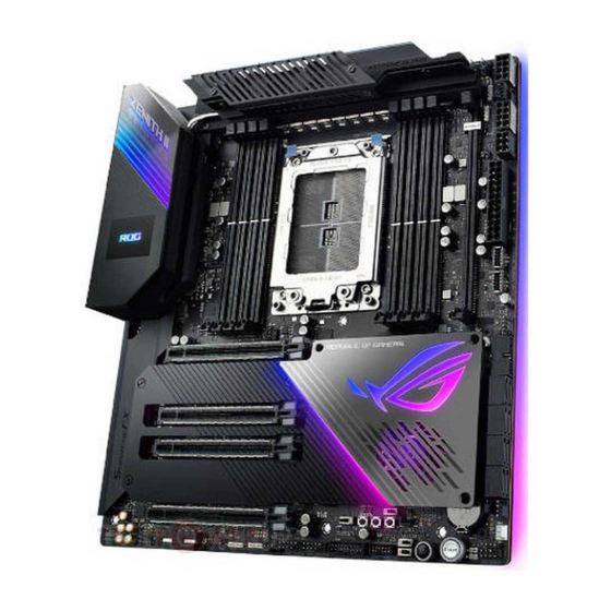
Page 18: Motherboard Layout
Motherboard layout Refer to Internal connectors and Rear I/O connection for more information about rear panel connectors and internal connectors. Chapter 1: Product Introduction... - Page 19 23. Full Speed Mode switch 1-13 24. BIOS Switch button 1-11 25. Node connector 1-24 26. ReTry button 1-10 27. Safe Boot button 1-10 28. M.2_3 switch 1-13 29. USB 2.0 connector 1-21 30. TPM connector 1-28 31. Front Panel Audio connector 1-25 32. M.2 slot 1-18 33. OLED connector 1-31 34. Water Block connector 1-24 ROG ZENITH II EXTREME...
-
Page 20: Central Processing Unit (Cpu)
Central Processing Unit (CPU) The motherboard comes with an AMD Socket sTRX4 for 3rd Gen AMD Ryzen™ Threadripper™ Desktop Processors. • The Socket sTRX4 has a different pinout design. Ensure that you use a CPU designed for the Socket sTRX4. • The CPU fits in only one correct orientation. DO NOT force the CPU into the socket to prevent bending the connectors on the CPU and damaging the CPU. • Ensure that all power cables are unplugged before installing the CPU. • Overclocking AMD processors, including without limitation, altering clock frequencies / multipliers or memory timing / voltage, to operate beyond their stock specifications will void any applicable AMD product warranty, even when such overclocking is enabled via AMD hardware and/or software. This may also void warranties offered by the system manufacturer or retailer. Users assume all risks and liabilities that may arise out of overclocking AMD processors, including, without limitation, failure of or damage to hardware, reduced system performance and/or data loss, corruption or vulnerability Chapter 1: Product Introduction... -
Page 21: System Memory
System memory The motherboard comes with Dual Inline Memory Modules (DIMM) slots designed for DDR4 (Double Data Rate 4) memory modules. A DDR4 memory module is notched differently from a DDR, DDR2, or DDR3 module. DO NOT install a DDR, DDR2, or DDR3 memory module to the DDR4 slot. Recommended memory configurations ROG ZENITH II EXTREME... - Page 22 Memory configurations You may install 4 GB, 8 GB, 16 GB, and 32 GB unbuffered ECC and non‑ECC DDR4 DIMMs into the DIMM sockets. You may install varying memory sizes in Channel A, Channel B, Channel C, and Channel D. The system maps the total size of the lower‑sized channel for the quad‑channel configuration. Any excess memory from the higher‑sized channel is then mapped for single-channel operation. • The default memory operation frequency is dependent on its Serial Presence Detect (SPD), which is the standard way of accessing information from a memory module. Under the default state, some memory modules for overclocking may operate at a lower frequency than the vendor‑marked value. • For system stability, use a more efficient memory cooling system to support a full memory load or overclocking condition. • Always install the DIMMS with the same CAS Latency. For an optimum compatibility, we recommend that you install memory modules of the same version or data code (D/C) from the same vendor. Check with the vendor to get the correct memory modules. • Visit the ASUS website for the latest QVL. Chapter 1: Product Introduction...
-
Page 23: Expansion Slots
Expansion slots Unplug the power cord before adding or removing expansion cards. Failure to do so may cause you physical injury and damage motherboard components. ROG ZENITH II EXTREME... - Page 24 Recommended VGA configuration 3rd Gen AMD Ryzen™ Threadripper™ Desktop Processors Slot Description Single VGA /CFX 3-Way SLI /CFX ® ® PCIE 4.0 x16_1 x16 PCIE 4.0 x16_2 PCIE 4.0 x16_3 PCIE 4.0 x16_4 * When the M.2_2 socket on board is operating in PCIe mode, PCIe 4.0 x16_4 will run at x4 mode. •...
-
Page 25: Onboard Buttons
Press the Power button to power up the system, or put the system into sleep or soft‑ off mode (depending on the operating system settings). The button also lights up when the system is plugged to a power source, indicating that you should shut down the system and unplug the power cable before removing or installing any motherboard component. FlexKey button (Reset) Press the FlexKey button to reboot the system. You may also configure the button and assign a quick access feature such as activating Safe Boot or turning Aura lighting on or off to the button. This button set to [Reset] by default. You can assign a different function to this button in the BIOS settings. ROG ZENITH II EXTREME... - Page 26 Safe Boot button The Safe Boot button temporarily applies safe settings to the BIOS while retaining the overclocked settings, allowing you to modify the settings causing a boot failure. Press this button at anytime to force the system to reboot into the BIOS safe mode. ReTry button The ReTry button is specially designed for overclockers and is most useful during the booting process where the Reset button is rendered useless. Press this button to force the system to reboot while retaining the same settings to be retried in quick succession to achieve a successful POST. Chapter 1: Product Introduction 1-10...
- Page 27 BIOS Switch button This motherboard comes with two BIOS chips. Press the BIOS Switch button to switch BIOS and load different BIOS settings. The nearby BIOS_LEDs indicate which BIOS is currently selected. ROG ZENITH II EXTREME 1-11...
-
Page 28: Onboard Switches
Onboard switches RSVD switch The RSVD switch is reserved for ASUS‑authorized technicians only. Please ensure the RSVD switch is set to Disabled. Setting this switch to Enabled may result in damages to your system. Slow Mode switch The system may crash due to the CPU being unstable when using extreme overclocking settings. Enable the Slow Mode switch during LN2 benching to decrease the processor frequency and stabilize the system, allowing you to keep track of the overclocking data. Chapter 1: Product Introduction 1-12... - Page 29 • DO NOT enable and disable this switch in short intervals! Doing so may damage the M.2 device connected to the M.2_3 slot. • If your system does not detect the M.2_3 slot when you switch the M.2_3 switch from disabled to enabled, please power off your system then switch it to enabled again, and then power on your system. The LED near this switch also lights up when the switch is set to disabled, and turned off when this switch is set to enabled. Full Speed Mode switch The Full Speed Mode switch allows you to set all connected fans to run at 100% PWM when enabled. ROG ZENITH II EXTREME 1-13...
-
Page 30: Onboard Jumpers
Onboard jumpers LN2 Mode jumper Set to pins 1‑2 to optimize the motherboard to remedy the cold‑boot bug during POST and help the system boot successfully. Chapter 1: Product Introduction 1-14... -
Page 31: Onboard Leds
Onboard LEDs Q LEDs The Q LEDs check key components (CPU, DRAM, VGA, and booting devices) during the motherboard booting process. If an error is found, the critical component’s LED stays lit up until the problem is solved. The Q LEDs provide the most probable cause of an error code as a starting point for troubleshooting. The actual cause may vary from case to case. Storage Device Activity LED The Storage Device Activity LED lights up or blinks when data is read from or written to the storage device or storage device add‑on card. ROG ZENITH II EXTREME 1-15... - Page 32 BIOS LED The BIOS LEDs indicate which BIOS chip is currently in use. 8-pin Power Plug LED The 8‑pin Power Plug LED lights up to indicate that the 8‑pin power plug is not connected. • DO NOT connect the 8‑pin power plug only, the motherboard may overheat under heavy usage. • Due to the CPU minimum power consumption requirement, we recommend using a PSU with 850W or above. Ensure to connect both the 8‑pin and 4‑pin power plugs (into another 8‑pin connector), or two 8‑pin power plugs or above to ensure system stability under heavy loading. Chapter 1: Product Introduction 1-16...
-
Page 33: Internal Connectors
1.10 Internal connectors SATA 6Gb/s connector The SATA 6Gb/s connector allows you to connect SATA devices such as optical disc drives and hard disk drives via a SATA cable. If you installed SATA storage devices, you can create a RAID 0, 1, and 10 configuration through the onboard AMD x590 chipset. • These connectors are set to [AHCI] by default. If you intend to create a Serial ATA RAID set using these connectors, set the SATA Mode Selection item in the BIOS to [RAID]. Before creating a RAID set, refer to the RAID Configuration Guide. You can • download the RAID Configuration Guide from the ASUS website. ROG ZENITH II EXTREME 1-17... - Page 34 ASMedia SATA 6 Gb/s connector ® The SATA 6Gb/s connector allows you to connect SATA devices such as optical disc drives and hard disk drives via a SATA cable. M.2 slot The M.2 slot allows you to install M.2 devices such as M.2 SSD modules. • M.2_1, M.2_2, and M.2_3 sockets support PCIe 4.0 x4 M Key design and type 2242 / 2260 / 2280 storage devices. • M.2_3 shares bandwidth with SATA6G_E1‑4; when the M.2_3 slot on board is operating in PCIe x4 mode, SATA6G_E1‑E4 will be disabled. The M.2 SSD module is purchased separately. Chapter 1: Product Introduction 1-18...
- Page 35 DIMM.2 slot The DIMM.2 slot allows you to install a DIMM.2 card to support additional M.2 SSD modules. • Before you install or remove the DIMM.2 card, ensure that the power supply is switched off or the power cord is detached from the power supply. Failure to do so may cause severe damage to the motherboard or DIMM.2 card. • The DIMM.2 card is notched to fit in only one orientation. Ensure that the notch on your card is aligned correctly with the DIMM.2 slot before inserting the card. DIMM.2 module supports PCIe 4.0 x4 and SATA mode M Key design and type 2242 / 2260 / 2280 / 22110 PCIe storage devices. The M.2 SSD module is purchased separately. ROG ZENITH II EXTREME 1-19...
- Page 36 USB 3.2 Gen 2 connector The USB 3.2 Gen 2 connector allows you to connect a USB 3.2 Gen 2 module for additional USB 3.2 Gen 2 ports. The USB 3.2 Gen 2 connector provides data transfer speeds of up to 10 Gb/s. The USB 3.2 Gen 2 module is purchased separately. USB 3.2 Gen 1 connector The USB 3.2 Gen 1 connector allows you to connect a USB 3.2 Gen 1 module for additional USB 3.2 Gen 1 ports. The USB 3.2 Gen 1 connector provides data transfer speeds of up to 5 Gb/s. The USB 3.2 Gen 1 module is purchased separately. The plugged USB 3.2 Gen 1 device may run on xHCI or EHCI mode depending on the operating system’s setting. Chapter 1: Product Introduction 1-20...
- Page 37 USB 2.0 connector The USB 2.0 connector allows you to connect a USB module for additional USB 2.0 ports. The USB 2.0 connector provides data transfer speeds of up to 480 MB/s connection speed. DO NOT connect a 1394 cable to the USB connectors. Doing so will damage the motherboard! • The SP_USB10 connector only supports single port USB 2.0 devices, we recommend you connect a single port device to this connector, and connect the chassis front panel USB 2.0 to the USB_E910 connector. • The USB 2.0 module is purchased separately. ROG ZENITH II EXTREME 1-21...
- Page 38 Fan and Pump connectors The Fan and Pump connectors allow you to connect fans or pumps to cool the system. • DO NOT forget to connect the fan cables to the fan connectors. Insufficient air flow inside the system may damage the motherboard components. These are not jumpers! Do not place jumper caps on the fan connectors! • Ensure the cable is fully inserted into the connector. For water cooling kits, connect the pump connector to the W_PUMP+1 or W_PUMP+2 connector, then connect the fan connectors to the CPU_FAN and CPU_OPT connectors. Header Max. Current Max. Power Default Speed Shared Control CPU_FAN Q‑Fan Controlled...
- Page 39 Chipset Fan connector The Chipset Fan connector is for connecting the chipset fan on the integrated heatsink. Liquid Cooling System connectors The Liquid Cooling System connectors allow you to connect sensors to monitor the temperature and flow rate of your liquid cooling system. You can manually adjust the fans and water pump to optimize the thermal efficiency of your liquid cooling system. ROG ZENITH II EXTREME 1-23...
- Page 40 Water Block connector The Water Block connector allows you to connect sensors to monitor the temperature, flow rate, and water leak signals of your third party monoblocks. You can manually adjust the fans and water pump to optimize the thermal efficiency of your third party monoblocks. Node connector The Node connector allows you to connect a compatible PSU or control a compatible fan extension card. Visit www.asus.com for more information about the devices and the latest compatibility list. Chapter 1: Product Introduction 1-24...
- Page 41 The Thermal Sensor connector allows you to connect a sensor to monitor the temperature of the devices and the critical components inside the motherboard. Connect the thermal sensor and place it on the device or the motherboard’s component to detect its temperature. The thermal sensor is purchased separately. Front Panel Audio connector The front panel audio connector is for a chassis‑mounted front panel audio I/O module that supports HD Audio. Connect one end of the front panel audio I/O module cable to this connector. We recommend that you connect a high‑definition front panel audio module to this connector to avail of the motherboard’s high‑definition audio capability. ROG ZENITH II EXTREME 1-25...
- Page 42 System Panel connector The System Panel connector supports several chassis‑mounted functions. • System Power LED connector (PLED) The 2‑pin connector allows you to connect the System Power LED. The System Power LED lights up when the system is connected to a power source, or when you turn on the system power, and blinks when the system is in sleep mode. • Storage Device Activity LED connector (HDLED) The 2‑pin connector allows you to connect the Storage Device Activity LED. The Storage Device Activity LED lights up or blinks when data is read from or written to the storage device or storage device add‑on card. • System Warning Speaker connector (SPEAKER) The 4-pin connector allows you to connect the chassis-mounted system warning speaker.
- Page 43 These Power connectors allow you to connect your motherboard to a power supply. The power supply plugs are designed to fit in only one orientation, find the proper orientation and push down firmly until the power supply plugs are fully inserted. • DO NOT connect the 8‑pin power plug only, the motherboard may overheat under heavy usage. • Due to the CPU minimum power consumption requirement, we recommend using a PSU with 850W or above. Ensure to connect both the 8‑pin and 4‑pin power plugs (into another 8‑pin connector), or two 8‑pin power plugs or above to ensure system stability under heavy loading. • For a fully configured system, we recommend that you use a power supply unit (PSU) that complies with ATX 12 V Specification 2.0 (or later version) and provides a minimum power of 350 W. • Connect the 4‑pin EZ_PLUG power plugs to ensure sufficient power when you install multiple graphics cards. • We recommend that you use a PSU with a higher power output when configuring a system with more power‑consuming devices. The system may become unstable or may not boot up if the power is inadequate. • If you want to use two or more high‑end PCIe x16 cards, use a PSU with 1000W power or above to ensure the system stability. ROG ZENITH II EXTREME 1-27...
- Page 44 TPM connector The TPM connector allows you to connect a Trusted Platform Module (TPM). A TPM securely stores keys, digital certificates, passwords, data, and also helps enhance network security, protect digital identities, and ensures platform integrity. The TPM is purchased separately. LED connector The LED connector is for connecting the LED PCB on your I/O cover. Chapter 1: Product Introduction 1-28...
- Page 45 Addressable Gen2 LED connector The Addressable Gen2 LED connector allows you to connect individually addressable RGB WS2812B LED strips or WS2812B based LED strips. The Addressable Gen2 LED connector supports WS2812B addressable RGB LED strips (5V/Data/Ground), with a maximum power rating of 3A (5V) and a maximum of 120 LEDs. Before you install or remove any component, ensure that the power supply is switched off or the power cord is detached from the power supply. Failure to do so may cause severe damage to the motherboard, peripherals, or components. • Actual lighting and color will vary with LED strip. • If your LED strip does not light up, check if the addressable RGB LED strip is connected in the correct orientation, and the 5V connector is aligned with the 5V header on the motherboard. • The addressable RGB LED strip will only light up when the system is powered on. • The addressable RGB LED strip is purchased separately. ROG ZENITH II EXTREME 1-29...
- Page 46 AURA RGB LED connector The AURA RGB LED connector allows you to connect RGB LED strips. The AURA RGB LED connector supports 5050 RGB multi‑color LED strips (12V/G/R/B), with a maximum power rating of 3A (12V). Before you install or remove any component, ensure that the power supply is switched off or the power cord is detached from the power supply. Failure to do so may cause severe damage to the motherboard, peripherals, or components. • Actual lighting and color will vary with LED strip. • If your LED strip does not light up, check if the RGB LED extension cable and the RGB LED strip is connected in the correct orientation, and the 12V connector is aligned with the 12V header on the motherboard. • The LED strip will only light up when the system is powered on. • The LED strip is purchased separately. Chapter 1: Product Introduction 1-30...
- Page 47 OLED connector The OLED connector allows you to connect the LiveDash OLED panel. The OLED panel provides you a quick overview of the system temperature, power status, and fan speeds when your system boots up. Use the Armoruy Crate or ROG LiveDash Utility to configure and customize the • LiveDash OLED panel. • The LiveDash OLED displays a Q‑Code that provides the most probable cause of an error code as a starting point for troubleshooting. The actual cause may vary from case to case. • Please refer to the Q‑Code table in the Appendix section for more details. ROG ZENITH II EXTREME 1-31...
-
Page 48: Probeit
1.11 ProbeIt The ROG ProbeIt allows you to detect your system’s current voltage and OC settings using a multimeter. You can also measure the ProbeIt points during overclocking. Using ProbeIt Connect one of the probe onto the GND ProbeIt point, then connect the other probe onto another ProbeIt point to measure the corresponding voltage information. The illustration above is for reference only, the actual motherboard layout and measure points may differ by model. Chapter 1: Product Introduction 1-32... -
Page 49: Chapter 2: Basic Installation
Chapter 2: Basic Installation Basic Installation Building your PC system The diagrams in this section are for reference only. The motherboard layout may vary with models, but the installation steps are the same for all models. 2.1.1 CPU installation The AMD Socket sTRX4 is compatible with 3rd Gen AMD Ryzen™ Threadripper™ Desktop Processors. - Page 50 Remove the external cap. External cap Rail frame PnP cap Slide the carrier frame with CPU into Carrier frame the rail frame until you hear a click with CPU sound, then remove the PnP cap. PnP cap Gently press down the rail frame until it latches to the socket housing, then press down the load plate.
- Page 51 Drive the three screws slightly into the holes in sequence 1>2>3, just enough to attach the load plate to the socket. When the three screws are attached, tighten them in sequence 1>2>3 to completely secure the load plate. Then apply the Thermal Interface Material to the CPU.
-
Page 52: Cooling System Installation
2.1.2 Cooling system installation To install the CPU heatsink and fan assembly: Chapter 2: Basic Installation... -
Page 53: Motherboard Installation
2.1.3 Motherboard installation Place the motherboard into the chassis, ensuring that its rear I/O ports are aligned to the chassis’ rear I/O panel. Place eight (8) screws into the holes indicated by circles to secure the motherboard to the chassis. •... -
Page 54: Dimm Installation
2.1.4 DIMM installation To remove a DIMM Chapter 2: Basic Installation... -
Page 55: Atx Power Connection
2.1.5 ATX power connection Ensure to connect the two 8-pin power plugs, or connect both the 8-pin and 4-pin power plugs (into another 8-pin connector). ROG ZENITH II EXTREM\E... -
Page 56: Sata Device Connection
2.1.6 SATA device connection Chapter 2: Basic Installation... -
Page 57: Front I/O Connector
2.1.7 Front I/O connector To install ASUS Q-Connector To install USB 3.2 Gen 2 connector USB 3.2 Gen 2 This connector will only fit in one orientation. Push the connector until it clicks into place. To install USB 3.2 Gen 1 connector To install USB 2.0 connector... -
Page 58: Expansion Card Installation
2.1.8 Expansion card installation To install PCIe x16 cards 2-10 Chapter 2: Basic Installation... - Page 59 To install FAN EXTENSION CARD II The illustrations in this section are for reference only. The chassis and motherboard layout may vary with models, but the installation steps are the same for all models. ROG ZENITH II EXTREM\E 2-11...
-
Page 60: Installation
2.1.9 M.2 installation Supported M.2 type varies per motherboard. 2-12 Chapter 2: Basic Installation... -
Page 61: Dimm.2 Installation
2.1.10 DIMM.2 installation • Supported M.2 type varies per motherboard. • The M.2 SSD module is purchased separately. ROG ZENITH II EXTREM\E 2-13... - Page 62 • Before you install or remove the DIMM.2 card, ensure that the ATX power supply is switched off or the power cord is detached from the power supply. Failure to do so may cause severe damage to the motherboard or DIMM.2 card. •...
-
Page 63: Wi-Fi Antenna Installation
2.1.11 Wi-Fi antenna installation Installing the ASUS 2x2 dual band W-Fi antenna Connect the bundled ASUS 2x2 dual band Wi-Fi antenna connector to the Wi-Fi ports at the back of the chassis. • Ensure that the ASUS 2x2 dual band Wi-Fi antenna is securely installed to the Wi-Fi ports. -
Page 64: Bios Update Utility
• Updating BIOS may have risks. If the BIOS program is damaged during the process and results to the system’s failure to boot up, please contact your local ASUS Service Center. 2-16... -
Page 65: Motherboard Rear And Audio Connections
Motherboard rear and audio connections 2.3.1 Rear I/O connection Rear panel connectors Clear CMOS button (CLR_CMOS). Press this button to clear the BIOS setup information only when the systems hangs due to overclocking. Wi-Fi 802.11 a/b/g/n/ac/ax, Bluetooth V5.0 USB 3.2 Gen 1 ports E34 LAN (RJ-45) port* USB 3.2 Gen 1 ports E12 10G LAN (RJ-45) port*... - Page 66 * LAN ports LED indications Activity Link LED Speed LED Status Description Status Description ACT/LINK SPEED No link 10 Mbps connection ORANGE Linked ORANGE 100 Mbps connection ORANGE Data activity GREEN 1 Gbps connection (Blinking) LAN port ORANGE Ready to (Blinking then wake up from Steady)
-
Page 67: Audio I/O Connections
2.3.2 Audio I/O connections Audio I/O ports Connect to Headphone and Mic Connect to Stereo Speakers Connect to 2-channel Speakers ROG ZENITH II EXTREM\E 2-19... - Page 68 Connect to 4-channel Speakers Connect to 5.1-channel Speakers Connect to 7.1-channel Speakers 2-20 Chapter 2: Basic Installation...
-
Page 69: Starting Up For The First Time
Starting up for the first time After making all the connections, replace the system case cover. Ensure that all switches are off. Connect the power cord to the power connector at the back of the system chassis. Connect the power cord to a power outlet that is equipped with a surge protector. Turn on the devices in the following order: Monitor External storage devices (starting with the last device on the chain) - Page 70 2-22 Chapter 2: Basic Installation...
-
Page 71: Chapter 3: Bios Setup
BIOS Setup Knowing BIOS The new ASUS UEFI BIOS is a Unified Extensible Interface that complies with UEFI architecture, offering a user-friendly interface that goes beyond the traditional keyboard- only BIOS controls to enable a more flexible and convenient mouse input. You can easily navigate the new UEFI BIOS with the same smoothness as your operating system. -
Page 72: Bios Setup Program
Clear CMOS button to clear RTC RAM. • The BIOS setup program does not support the Bluetooth devices. Please visit ASUS website for the detailed BIOS content manual. BIOS menu screen The BIOS Setup program can be used under two modes: EZ Mode and Advanced Mode. -
Page 73: Advanced Mode
Menu bar Language MyFavorite(F3) Qfan Control(F6) AURA ON/OFF(F4) Menu items General help Last modified settings Hot Keys Go back to EZ Mode Search on the FAQ Displays a quick overview of the system status and prediction ROG ZENITH II EXTREME... - Page 74 Menu bar The menu bar on top of the screen has the following main items: My Favorites For saving the frequently-used system settings and configuration. Main For changing the basic system configuration Extreme Tweaker For changing the overclocking settings Advanced For changing the advanced system settings For displaying the system temperature, power status, and changing Monitor...
- Page 75 Move your mouse over this button to show a QR code, scan this QR code on your mobile device to connect to the BIOS FAQ web page of the ASUS support website. You can also scan the following QR code: Hot keys This button above the menu bar contains the navigation keys for the BIOS setup program.
-
Page 76: Ez Mode
3.2.2 EZ Mode The EZ Mode provides you an overview of the basic system information, and allows you to select the display language, system performance, mode and boot device priority. To access the Advanced Mode, select Advanced Mode or press the <F7> hotkey for the advanced BIOS settings. -
Page 77: Q-Fan Control
Click to activate DC Mode configured PWM Mode Select a profile to Click to apply the fan setting apply to your fans Click to undo the Click to go back to main menu changes Select to manually configure your fans ROG ZENITH II EXTREME... - Page 78 Configuring fans manually Select Manual from the list of profiles to manually configure your fans’ operating speed. Speed points Select to manually configure your fans To configure your fans: Select the fan that you want to configure and to view its current status. Click and drag the speed points to adjust the fans’...
-
Page 79: Ez Tuning Wizard
Press <F11> on your keyboard or click EZ Tuning Wizard(F11) from the BIOS screen to open EZ Tuning Wizard screen. Click OC then click Next. Select a PC scenario Daily Computing or Gaming/Media Editing, then click Next. ROG ZENITH II EXTREME... - Page 80 Select a Main Cooling System BOX cooler, Tower cooler, Water cooler, or I’m not sure, then click Next. After selecting the Main Cooling System, click Next then click Yes to start the OC Tuning. Chapter 3: BIOS Setup 3-10...
-
Page 81: My Favorites
My Favorites is your personal space where you can easily save and access your favorite BIOS items. My Favorites comes with several performance, power saving, and fast boot related items by default. You can personalize this screen by adding or removing items. ROG ZENITH II EXTREME 3-11... - Page 82 Adding items to My Favorites To add BIOS items: Press <F3> on your keyboard or click MyFavorite(F3) from the BIOS screen to open Setup Tree Map screen. On the Setup Tree Map screen, select the BIOS items that you want to save in My Favorites screen.
-
Page 83: Main Menu
This item allows you to set the BCLK frequency to enhance the system performance. Use the <+> or <-> to adjust the value. We recommend you to set the value based on the CPU specification, as high BCLK frequencies may damage the CPU permanently. ROG ZENITH II EXTREME 3-13... -
Page 84: Advanced Menu
Custom CPU Core Ratio This item allows you to set a custom CPU core ratio. The CPU core ratio is calculated with the formula: 2 * FID / DID. Configuration options: [Auto] [Manual] The following items appear only when you set the Custom CPU Core Ratio to [Manual]. This item allows you to set the core frequency multiplier. -
Page 85: Sata Configuration
This item allows you to use the Azalia High Definition Audio Controller. Configuration options: [Disabled] [Enabled] CPU PCIE Link Mode This item allows you to set the M.2/PCIE link speed. Configuration options: [Auto] [GEN 1] [GEN 2] [GEN 3] ROG ZENITH II EXTREME 3-15... - Page 86 SB PCIE Link Mode This item allows you to set the Southbridge link speed. Configuration options: [Auto] [GEN 1] [GEN 2] [GEN 3] PCIEX16_1 Bandwidth [X16 Mode] The PCIe x16_1 slot runs at x16 mode. [PCIe RAID Mode] The four PCIe x16 slots run at x4+x4+x4+x4 mode, which allows you to create a RAID array for up to 4 PCIe devices.
-
Page 87: Apm Configuration
This item allows you to enable or disable the RTC (Real-Time Clock) to generate a wake event and configure the RTC alarm date. When enabled, you can set the days, hours, minutes, or seconds to schedule an RTC alarm date. Configuration options: [Disabled] [Enabled] ROG ZENITH II EXTREME 3-17... -
Page 88: Cpu Configuration
3.6.6 CPU Configuration The items in this menu show the CPU-related information that the BIOS automatically detects. The items in this menu may vary based on the CPU installed. NX Mode This item allows you enable or disable No-execute page protection function. Configuration options: [Disabled] [Enabled] SVM Mode This item allows you enable or disable CPU Virtualization. -
Page 89: Monitor Menu
Accelerates the boot speed on the next boot after an AC power loss. Boot Configuration Boot Logo Display [Auto] Sets the boot logo to display during POST. [Full Screen] Sets the boot logo display in full screen during POST. [Disabled] Disables the boot logo display during POST. ROG ZENITH II EXTREME 3-19... - Page 90 Setup Mode [Advanced Mode] This item allows you to go to Advanced Mode of the BIOS after POST. [EZ Mode] This item allows you to go to EZ Mode of the BIOS after POST. CSM (Compatibility Support Module) This item allows you to configure the CSM (Compatibility Support Module) items to fully support the various VGA, bootable devices and add-on devices for better compatibility.
-
Page 91: Tool Menu
3.9.1 ASUS EZ Flash 3 Utility This item allows you to run ASUS EZ Flash 3. When you press <Enter>, a confirmation message appears. Use the left/right arrow key to select between [Yes] or [No], then press <Enter> to confirm your choice. -
Page 92: Secure Erase
Locked. SSDs might be locked if the Secure Erase process is either incomplete • or was stopped. This may be due to a third party software that uses a different password defined by ASUS. You have to unlock the SSD in the software before proceeding with Secure Erase. Chapter 3: BIOS Setup... -
Page 93: Asus Overclocking Profile
3.9.6 ASUS Armoury Crate This item allows you to enable or disable the ASUS Armoury Crate. The ASUS Armoury Crate is a fixed Advanced Configuration and Power Interface (ACPI) table that provides Windows with a platform binary that the operating system can execute. -
Page 94: Graphics Card Information
GPU Post This item displays the information and recommended configuration for the PCIE slots that the graphics card is installed in your system. This feature is only supported on selected ASUS graphics cards. 3.10 Exit menu The Exit menu items allow you to load the optimal default values for the BIOS items, and save or discard your changes to the BIOS items. -
Page 95: Updating Bios
3.11 Updating BIOS The ASUS website publishes the latest BIOS versions to provide enhancements on system stability, compatibility,and performance. However, BIOS updating is potentially risky. If there is no problem using the current version of BIOS, DO NOT manually update the BIOS. -
Page 96: Asus Ez Flash 3
3.11.2 ASUS EZ Flash 3 ASUS EZ Flash 3 allows you to download and update to the latest BIOS through the Internet without having to use a bootable floppy disk or an OS-based utility. Updating through the Internet varies per region and Internet conditions. Check your local Internet connection before updating through the Internet. - Page 97 To update the BIOS by Internet: Enter the Advanced Mode of the BIOS setup program. Go to the Tool menu to select ASUS EZ Flash 3 Utility and press <Enter>. Select via Internet. Press the Left/Right arrow keys to select an Internet connection method, and then press <Enter>.
-
Page 98: Asus Crashfree Bios 3
3.11.3 ASUS CrashFree BIOS 3 The ASUS CrashFree BIOS 3 utility is an auto recovery tool that allows you to restore the BIOS file when it fails or gets corrupted during the updating process. You can restore a corrupted BIOS file using the motherboard support USB drive that contains the BIOS file. -
Page 99: Chapter 4: Raid Support
The motherboard comes with the RaidXpert2 Configuration Utility that supports Volume, RAIDABLE, RAID 0, RAID 1, and RAID 10 (depends on system licensing) configurations. For more information on configuring your RAID sets, please refer to the RAID Configuration Guide which you can find at https://www.asus.com/support. 4.1.1 RAID definitions Volume provides the ability to link-together storage from one or several disks, regardless of the size of the space on those disks. - Page 100 Chapter 4: RAID Support...
-
Page 101: Appendix
CPU self test failed or possible CPU cache error CPU micro-code is not found or micro-code update is failed Internal CPU error Reset PPI is not available 5C – 5F Reserved for future AMI error codes (continued on the next page) ROG ZENITH II EXTREME... - Page 102 Q-Code table Code Description S3 Resume is stared (S3 Resume PPI is called by the DXE IPL) S3 Boot Script execution Video repost OS S3 wake vector call E4 – E7 Reserved for future AMI progress codes S3 Resume Failed S3 Resume PPI not Found S3 Resume Boot Script Error S3 OS Wake Error...
- Page 103 Reserved for ASL (see ASL Status Codes section below) Ready To Boot event Legacy Boot event Exit Boot Services event Runtime Set Virtual Address MAP Begin Runtime Set Virtual Address MAP End Legacy Option ROM Initialization System Reset (continued on the next page) ROG ZENITH II EXTREME...
- Page 104 Q-Code table Code Description USB hot plug PCI bus hot plug Clean-up of NVRAM Configuration Reset (reset of NVRAM settings) B8– BF Reserved for future AMI codes CPU initialization error System Agent initialization error PCH initialization error Some of the Architectural Protocols are not available PCI resource allocation error.
-
Page 105: Notices
Notices FCC Compliance Information Responsible Party: Asus Computer International Address: 48720 Kato Rd., Fremont, CA 94538, USA Phone / Fax No: (510)739-3777 / (510)608-4555 Identification of the assembled product: INTEL WI-FI 6 AX200 ® Identification of the modular components used in the assembly:... - Page 106 Compliance Statement of Innovation, Science and Economic Development Canada (ISED) This device complies with Innovation, Science and Economic Development Canada licence exempt RSS standard(s). Operation is subject to the following two conditions: (1) this device may not cause interference, and (2) this device must accept any interference, including interference that may cause undesired operation of the device.
- Page 107 ASUS Recycling/Takeback Services ASUS recycling and takeback programs come from our commitment to the highest standards for protecting our environment. We believe in providing solutions for you to be able to responsibly recycle our products, batteries, other components as well as the packaging materials.
- Page 108 NCC: Taiwan Wireless Statement 經型式認證合格之低功率射頻電機,非經許可,公司、商號或使用者均不得擅自變更頻 率、加大功率或變更原設計之特性及功能。低功率射頻電機之使用不得影響飛航安全及 干擾合法通信;經發現有干擾現象時,應立即停用,並改善至無干擾時方得繼續使用。 前項合法通信,指依電信法規定作業之無線電通信。低功率射頻電機須忍受合法通信或 工業、科學及醫療用電波輻射性電機設備之干擾。 應避免影響附近雷達系統之操作。 Japan RF Equipment Statement 屋外での使用について 本製品は、 5GHz帯域での通信に対応しています。 電波法の定めにより5.2GHz、 5.3GHz帯域の電 波は屋外で使用が禁じられています。 法律および規制遵守 本製品は電波法及びこれに基づく命令の定めるところに従い使用してください。 日本国外では、 その国の法律または規制により、 本製品の使用ができないことがあります。 このような国では、 本 製品を運用した結果、 罰せられることがありますが、 当社は一切責任を負いかねますのでご了承 ください。 Précautions d’emploi de l’appareil : Soyez particulièrement vigilant quant à votre sécurité lors de l’utilisation de cet appareil dans certains lieux (les avions, les aéroports, les hôpitaux, les stations- service et les garages professionnels).
- Page 109 ASUSTek Computer Inc. hereby declares that this device is in compliance zahtjevima i ostalim odgovarajućim odredbama direktive 2014/53/EU. Cijeli with the essential requirements and other relevant provisions of Directive tekst EU izjave o sukladnosti dostupan je na https://www.asus.com/support/ 2014/53/EU. Full text of EU declaration of conformity is available at https://www.asus.com/support/ WiFi koji radi na opsegu frekvencija 5150-5350 MHz bit će ograničen na...
- Page 110 ASUSTek Computer Inc. tukaj izjavlja, da je ta naprava skladna s temeljnimi Pilns ES atbilstības paziņojuma teksts pieejams šeit: zahtevami in drugimi relevantnimii določili Direktive 2014/53/EU. Polno https://www.asus.com/support/ besedilo izjave EU o skladnosti je na voljo na https://www.asus.com/ Wi-Fi darbība 5150–5350 MHz ir jāierobežo lietošanai telpās valstīs, kuras support/ norādītas tālāk.
- Page 111 5725 - 5850 MHz 8.99 dBm Bluetooth 2402 - 2480 MHz 12.53 dBm For the standard EN 300 440 V2.1.1, if this device operates in 5725-5875 MHz, it will be considered as a receiver category 2. ROG ZENITH II EXTREME A-11...
-
Page 112: Asus Contact Information
+1-510-608-4555 Web site http://www.asus.com/us/ Technical Support Support fax +1-812-284-0883 Telephone +1-812-282-2787 Online support https://www.asus.com/support/Product/ContactUs/ Services/questionform/?lang=en-us ASUS COMPUTER GmbH (Germany and Austria) Address Harkort Str. 21-23, 40880 Ratingen, Germany +49-2102-959931 Web site http://www.asus.com/de Online contact http://eu-rma.asus.com/sales Technical Support Telephone +49-2102-5789555 Support Fax...
Need help?
Do you have a question about the Rog Zenith II Extreme and is the answer not in the manual?
Questions and answers