Advertisement
Quick Links
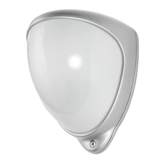
D-TECT 60
GJD320 60m PIR Detector
PACKAGE CONTENTS
•
1 x D-TECT 60
•
1 x Drilling template for fixing holes
•
3 x 31.75mm wall plugs
•
3 x 31.75mm screws
•
2 x Tamper Feet
•
1 x Installation manual
INTRODUCTION
The D-TECT 60 is an outdoor motion detector and alarm
trigger. The D-TECT 60 delivers precise, reliable presence
detection.
QUICK INSTALLATION
1.
Mount and connect the detector following the
instructions given later in this sheet.
2.
Apply supply voltage to the unit. The blue detection
LED flashes three times.
3.
Wait approximately 2 to 3 minutes to allow the
detector to settle.
Note: The front cover must be fitted when walk testing.
The default settings are:
•
Range: 60 metres
•
Pulse count: 1
•
Detection LED: off
MOUNTING THE UNIT
WARNING
•
NYLON WASHERS PROVIDED MUST BE USED
WITH SCREWS
•
ENSURE CABLE ENTRY AND SCREW HOLES
ARE SEALED WITH WATER BASED SEALANT
•
DO NOT USE SILICONE BASED SEALANT
During installation, protect the electronics against water, as
trapped moisture can affect or damage the unit.
1.
Drill the wall to accept the two fixing screws, the
cable entry, and the tamper cup (if used). See
Figures 1 and 2. A hole-drilling template is provided.
Note: We recommend using the tamper cup on uneven
wall surfaces.
2.
Remove the cover assembly by loosening the locking
screw. The cover hinges from the top and lifts out of
the location slot. See Figure 3.
3.
Feed standard eight-core alarm cable into the cable
entry. Bare the wires and connect 6 wires to the
terminal block and optionally connect 2 to the tamper
board. See Figures 2, 4, 5, 6 & 7.
4.
Screw the unit to the wall ensuring that the tamper
pin is correctly located and that the tamper switch is
closed. See Figure 7.
To aid installation, two spare tamper feet are provided. One
is 1mm longer and the other is 2mm longer than the tamper
foot originally fitted. The tamper foot is a push fit and can
be removed by carefully pulling it from the pin. See Figure
2.
5.
When the detector is aligned, connected, and
programmed to suit the installation, replace the front
cover and lock as shown. See Figure 8.
ALIGNMENT & MASKING
The PIR circuitry detects changes in heat and movement
in the beam pattern; therefore items such as trees, shrubs,
ponds, boiler flues, and animals should be considered
when positioning the detector.
Note: The PIR sensor is more sensitive to movement
across the beams, and less sensitive to movement directly
towards or away from the beams.
When coverage exceeds the desired detection area, adjust
the module as required and mask off any beams, either
vertically or horizontally, to avoid unwanted detection.
PROGRAMMING
To change any of the detector's settings change the
configuration of the programming switches (see Figure 11).
PROGRAMMING CHART
Option
Range 40 metres
Range 60 metres
Pulse count 1
Pulse count 2
LED Off
LED On
PROGRAMMING OPTIONS DEFINITIONS
Pulse Count
This is the number of times the unit has to detect before
signaling an output.
LED
LED Off – LED disabled.
LED On – LED signals a detection.
1
Detect. Illuminate. Deter
Switch Configuration
Switch 1 off
Switch 1 on
Switch 2 off
Switch 2 on
Switch 3 off
Switch 3 on
Advertisement

Subscribe to Our Youtube Channel
Related Manuals for GJD D-TECT 60


Summary of Contents for GJD D-TECT 60
- Page 1 1 x Installation manual be removed by carefully pulling it from the pin. See Figure INTRODUCTION The D-TECT 60 is an outdoor motion detector and alarm When the detector is aligned, connected, and trigger. The D-TECT 60 delivers precise, reliable presence programmed to suit the installation, replace the front detection.
-
Page 2: Specifications
In walk test mode, the detection LED option is set to ON, Detection Area Programmable between 40 & 60 metres and the pulse count option is set to 1. The detection LED lights each time the D-Tect 60 detects your presence. Coverage 60m x 6m coverage max. Adjustment... - Page 5 2.6m 84º 28º 11.3º...
- Page 6 ENGINEER NOTES w: www.gjd.co.uk t: +44 (0) 1706 363 998 f: +44 (0) 1706 363 991 Unit 2, Birch Business Park, Whittle Lane, He ywood, Greater Manchester, OL10 2SX, UK...
Need help?
Do you have a question about the D-TECT 60 and is the answer not in the manual?
Questions and answers