Advertisement
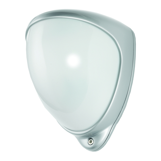
D-TECT Dual T ech
GJD360/AM Movement Detector
INTRODUCTION
A CCTV event trigger utilising two independent passive
infrared detectors combined in a T05 package and a
microwave sensor. Both PIR sensors and the microwave
have to trigger before the detector signals an alarm. The
high precision, very reliable presence detector has been
designed for use within CCTV installations and will alarm if
tampered by masking.
The integral dual axis tilt sensor allows 180° of pan
and 90° tilt. This increases the speed of the outdoor
installation and provides incredibly accurate aiming of
the detection pattern. The electronics module is acrylic
coated for additional component stability. It is encased in
a vandal-resistant high impact zinc alloy housing with a
UV stabilised translucent front cover ensuring the sensor
is impervious to and unaffected by weather conditions.
Additionally the combination of precision electronics,
digital white light filter and double shielding eliminates
false alarms from the sun and other visible light sources.
The DUAL TECH AM design gives a neat and
professional appearance with no visible indication of the
orientation of the detector head, and totally hides the
wiring.
QUICK INSTALLATION GUIDE
Apply supply voltage to the unit, the amber led flashes 10
times, then the blue LED flashes 3 times.
The detector takes approximately 2-3 minutes to settle.
The walk test led is factory set to OFF. Pressing the
program button once will enable the walk test LED for 5
minutes.
THE FRONT COVER MUST BE FITTED WHEN WALK
TESTING
FACTORY SETTINGS ARE:
1 RANGE 30 METRES
2 PULSE COUNT 1
3 LED OFF
When enabled the D-TECT DUAL TECH AM has four LED
indicators.
Green - Microwave detection
Red - Both PIRs detection
Blue - Alarm output, both PIRs and microwave detection
Amber - Anti-Mask detection
ANTI-MASKING CIRCUIT
The cover must be fitted before applying power to the
detector.
During the first 10 seconds after power has been
connected, the amber LED flashes and the anti-masking
circuit starts to self calibrate. The amber LED indicates
when the detector is covered, but the relay contacts do not
operate until the unit has been covered for 60 seconds.
SEQUENCE FOR CORRECT OPERATION
1. Make connection and replace cover.
2. Apply 12 volts power. Amber LED Flashes 10 times -
self calibration completed.
3. Cover detector for 60 seconds. When anti-mask
detection is continuous for 60 seconds the normally closed
relay will open until anti-mask detection is cleared.
STAGE 1 - Mounting the unit
- During installation the electronics must be protected
against water, as trapped moisture can affect or damage
the unit.
1. Using the template provided drill the wall to accept the
two fixing screws, the cable entry and the tamper cup (if
used). See fig 1 and 2.
Note: We recommend using the tamper cup on uneven
wall surfaces.
2. Remove the cover assembly by loosening the locking
screw. The cover hinges from the top and lifts out of the
location slot. See fig 3.
3. Feed standard 8 core alarm cable into the cable entry;
bare the wires and connect to the terminal block as shown
in fig 7. Screw the unit to the wall ensuring that the tamper
pin is correctly located and that the tamper microswitch
is closed. See fig 4 and 5. To aid installation, two spare
tamper feet are provided. One is 1mm longer and the
other is 2mm longer than the tamper foot originally fitted.
The tamper foot is a push fit and can be removed by
carefully pulling it from the pin. See fig 2.
4. Always ensure when replacing the electronics module
that the LED is facing forward so as to ensure correct
alignment of the beam pattern. (Refer section titled
"Multibeam Alignment & Masking").
5. When the detector has been aligned to suit the
installation,replace the front cover and lock as shown. See
fig 6.
Advertisement
Table of Contents

Related Manuals for GJD D-TECT Dual Tech GJD360/AM


Summary of Contents for GJD D-TECT Dual Tech GJD360/AM
- Page 1 D-TECT Dual T ech GJD360/AM Movement Detector INTRODUCTION SEQUENCE FOR CORRECT OPERATION A CCTV event trigger utilising two independent passive 1. Make connection and replace cover. infrared detectors combined in a T05 package and a microwave sensor. Both PIR sensors and the microwave 2.
-
Page 2: Beam Pattern
Beam Pattern STAGE 3 - Multibeam Alignment & Masking The GJD multifunction lens fitted to the D-TECT detector produces 7 long range beams and 7 medium to short range curtain beams. Movement across the beams... -
Page 3: Programming Chart
2. Wait four seconds until the blue LED indicator goes off. ACCESSORIES 3. The indicator will then flash out the existing setting. GJD is able to supply the following accessories to aid installations: 4. To change the setting for that option, press the button the number of times required for the new setting. - Page 4 Figure 1 Optional for Tamper Cup Cable Holes Template Figure 2 Figure 3 Figure 4 Figure 5 Figure 6...
- Page 5 Figure 7 Figure 8 ALARM/NC TAMPER ALARM/NO 9-15 Figure 9 Figure 10 Program Button PROGRAM ALARM/NC TAMPER ALARM/NO 9-15 Blue LED...
-
Page 6: Simplified Eu Declaration Of Conformity
SIMPLIFIED EU DECLARATION OF CONFORMITY Hereby, GJD Manufacturing Ltd declares that the radio equipment type GJD360AM Dualtech Anti-Mask Detector is in compliance with Directive 2014/53/EU. The full text of the EU declaration of conformity is available at the following internet address: gjd.co.uk... - Page 7 ENGINEER NOTES www.gjd.co.uk info@gjd.co.uk +44 (0) 1706 363 998 Unit 2 Birch Business Park, Whittle Lane, Heywood, Greater Manchester, OL10 2SX, UK...
Need help?
Do you have a question about the D-TECT Dual Tech GJD360/AM and is the answer not in the manual?
Questions and answers