
Related Manuals for PiezoDrive PX200


Summary of Contents for PiezoDrive PX200
- Page 1 PX200 Power Amplifier Manual and Specifications Hardware Version 5 Revision History Date Revision Changes 15/05/22 1 Document published PX200 V5 Manual 13/05/2022...
-
Page 2: Table Of Contents
Front Panel ..........................11 Signal Path ..........................12 Voltage Limits ........................... 13 Bias Outputs and Piezo Benders ....................13 Overload and Shutdown ......................13 Bridged Mode ........................... 15 Rack Mounting .......................... 16 Delivery Contents ........................16 Warranty ..........................16 PX200 V5 Manual 13/05/2022... -
Page 3: Introduction
Two amplifiers can be connected in bridge-mode to provide up to +/-200V or +400V. The PX200 has a high output current up to 13 Amps peak and is well suited to precision applications that require high power and frequency. -
Page 4: Output Voltage Ranges
The output voltage range is specified when ordering. The standard voltage ranges and associated current limits are listed below. Since the PX200 has front panel controls for reducing the positive and negative output voltage range, choose a range equal to or slightly greater than required. -
Page 5: Output Current
5 Power Bandwidth Launch Online Power Bandwidth Calculator The online power bandwidth calculator estimates the highest achievable frequency with a capacitive load impedance. The calculator considers the current limit, slew-rate, output impedance, and small- signal bandwidth. PX200 V5 Manual 13/05/2022... - Page 6 Table 2. Maximum frequency (Hz) versus load capacitance and output voltage span In the above table, the frequencies limited by slew-rate are marked with an asterisk. The slew-rate is approximately 35 V/uS which implies a maximum frequency of 35 × 10 ������ �� ���� ���� PX200 V5 Manual 13/05/2022...
-
Page 7: Pulse Current Option
The maximum pulse duration versus peak current is described in Figure 1. The pulse current option can be ordered by appending the order code with “-PULSE”, e.g. “PX200-P200-PULSE”. Figure 1. Maximum pulse duration versus peak current for each voltage span... -
Page 8: Specifications
LEMO 0B, LEMO 00, Screw Terminals, BNC Power Supply 90 Vac to 250 Vac Environment 0-40 C (32-104 F) Non-condensing humidity Dimensions 212 x 304.8 x 88 mm (8.35 x 12 x 3.46 in) Weight 2 kg (4.4 lb) PX200 V5 Manual 13/05/2022... -
Page 9: Small Signal Bandwidth
100 nF 367 kHz 300 nF 208 kHz 1 uF 88 kHz 3 uF 30 kHz 10 uF 9.3 kHz 30 uF 3.7 kHz 110 uF 1.3 kHz Table 4. Small signal bandwidth versus load capacitance (-3dB) PX200 V5 Manual 13/05/2022... -
Page 10: Noise
10 uF 9.3 kHz 56 uV 132 uV 30 uF 3.7 kHz 52 uV 131 uV 100 uF 1.3 kHz 47 uV 129 uV Table 5. RMS noise versus load capacitance (0.03 Hz to 1 MHz) PX200 V5 Manual 13/05/2022... -
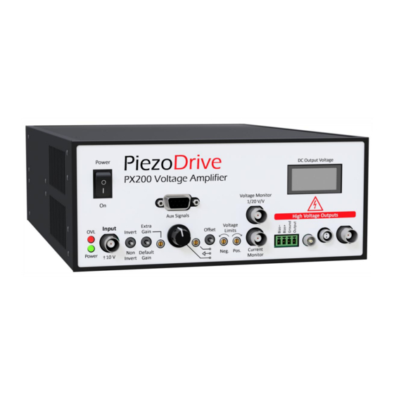
Page 11: Front Panel
LEMO 0B Output Output FGG.0B.302 connector, suits LEMO FGG.0B.302 cable plug BNC Output Output Suits male BNC cable plug DC Output Volt. Display showing average output voltage The mating connector for the 4-way screw terminal connector is OQ0432510000G. PX200 V5 Manual 13/05/2022... -
Page 12: Signal Path
11 Signal Path Offset Knob zero Offset Pot Offset Switch Gain Pot Output Input Voltage Limits Extra Gain Power Amplifier Invert Switch See Table 1 for Gain Switch Figure 5. Signal path with switches in default positions. PX200 V5 Manual 13/05/2022... -
Page 13: Voltage Limits
For example, a PX200-N100-P100 (with a +/-100V output range) will output +100V and -100V on HV+ and HV- respectively. For amplifier configurations where the HV- output is zero (e.g. - Page 14 ���� where �� is the peak-to-peak displacement of the bender. ���� References A New Electrical Configuration for Improving the Range of Piezoelectric Bimorph Benders; S. A. Rios, A. J. Fleming; Sensors and Actuators A: Physical, 2015. PX200 V5 Manual 13/05/2022...
-
Page 15: Bridged Mode
±200V 1.5 A PX200-N100-P100 PX200-N100-P100 ±100V 3.1 A PX200-N50-P50 PX200-N50-P50 0V to 200V 3.1 A PX200-P100 PX200-N100 0V to 300V 2.1 A PX200-P150 PX200-N150 0V to 400V 1.5 A PX200-P200 PX200-N200 Table 7. Common bridge-mode configurations PX200 V5 Manual 13/05/2022... -
Page 16: Rack Mounting
16 Rack Mounting The PX200 can be installed in a 19-inch x 2U rack space using the single unit rack kit (order code: SingleRackKit-2U). Two amplifiers can also be installed in a side-by-side configuration using the double unit rack kit (order code: DoubleRackKit-2U).
Need help?
Do you have a question about the PX200 and is the answer not in the manual?
Questions and answers