
Related Manuals for PiezoDrive PD200X4-V0,200


Summary of Contents for PiezoDrive PD200X4-V0,200
- Page 1 PD200X4 – Four Channel Power Amplifier Manual and Specifications Hardware Version 2 Revision History Date Revision Changes 12/01/21 1 Document created PD200X4 V2 Manual Modified 13/01/2021...
-
Page 2: Table Of Contents
Contents Introduction ............................3 Warnings / Notes ..........................3 Output Voltage Ranges ........................4 Output Current ..........................4 Specifications ............................. 5 Signal Path ............................6 Bridged Mode ............................ 7 Overload and Shutdown ........................8 Pulse Current Option ......................... 9 Power Bandwidth .......................... 10 Small Signal Bandwidth ......................... -
Page 3: Introduction
1 Introduction The PD200X4 is a four-channel linear amplifier for driving piezoelectric actuators and other loads. The output voltage range can be unipolar, bipolar, or asymmetric from 50V to 200V. Up to +/-200V can be achieved using two channels with a bridged load. Refer to the specifications table for the available output voltage ranges. -
Page 4: Output Voltage Ranges
Peak Order Voltage Mode Voltage Current Current Code 0 to +200 V 200 V 0.57 A PD200X4-V0,200 0 to +150 V 150 V 0.91 A PD200X4-V0,150 0 to +100 V 100 V 1.20 A PD200X4-V0,100 -50 to +150 V 200V 0.57 A... -
Page 5: Specifications
* For AC signals greater than 100 Hz. The total RMS current limit for all four channels is 2.6 Arms, which can occur with 100 Vp-p and 150 Vp-p models, or with large load capacitances with a power bandwidth less than 100 Hz. **A 3D Model is available at www.piezodrive.com PD200X4 V2 Manual Modified 13/01/2021... -
Page 6: Signal Path
6 Signal Path The signal paths for channels 1 and 2 are shown in Figure 1, which are identical to channels 3 and 4. The signal path includes a DC offset and voltage limit, which are set by front panel controls. The DC offset function can be disabled with the –OSD option, e.g. -
Page 7: Bridged Mode
7 Bridged Mode In bridged mode, two channels are connected in series to double the output voltage range and power. For example, the PD200X4-V100,100 has four independent channels with a range of +/-100 V. When the Bridge Mode switch is enabled, channel 2 is inverting, which results in +/-200 V across the load. -
Page 8: Overload And Shutdown
Figure 3. Calculator inputs for driving a bridged 1uF load with +/-200V. The recommended order codes for bridge-mode operation are listed in Table 2. Note that any PD200X4 amplifier can be operated with a bridged load; however, asymmetric voltage ranges (e.g. 0V to +200V) require the inversion function to be implemented externally. -
Page 9: Pulse Current Option
For applications that require a high peak current, the peak current limit can be increased to 10 Amps by appending the order code with “-PULSE”, e.g. “PD200X4-V0,200-PULSE”. In this configuration, the average current limit remains the same; however, the peak current limit is increased to 10 Amps and the maximum pulse duration is reduced to the time listed in Table 3. -
Page 10: Power Bandwidth
10 Power Bandwidth Launch Online Power Bandwidth Calculator The online power bandwidth calculator takes into account the current limit, slew-rate, output impedance, and small-signal bandwidth. With a capacitive load, the RMS current for a sine-wave is �� ������ ���� �� ������... - Page 11 The maximum peak-to-peak voltage is plotted against frequency in Figure 5. Figure 5. Maximum peak-to-peak voltage versus frequency and load capacitance PD200X4 V2 Manual Modified 13/01/2021...
-
Page 12: Small Signal Bandwidth
11 Small Signal Bandwidth The small-signal frequency response and -3 dB bandwidth is described in Figure 6 and Table 5. 3 uF 1 uF 300 nF 100 nF 30 nF 10 nF 30 uF 10 uF -100 -150 -200 Frequency (Hz) Figure 6. -
Page 13: Noise
12 Noise The output noise contains a low frequency component (0.03 Hz to 20 Hz) that is independent of the load capacitance; and a high frequency (20 Hz to 1 MHz) component that is approximately inversely proportional to the load capacitance. The noise is measured with a preamplifier with a gain of 1000, an oscilloscope, and Agilent 34461A Voltmeter. -
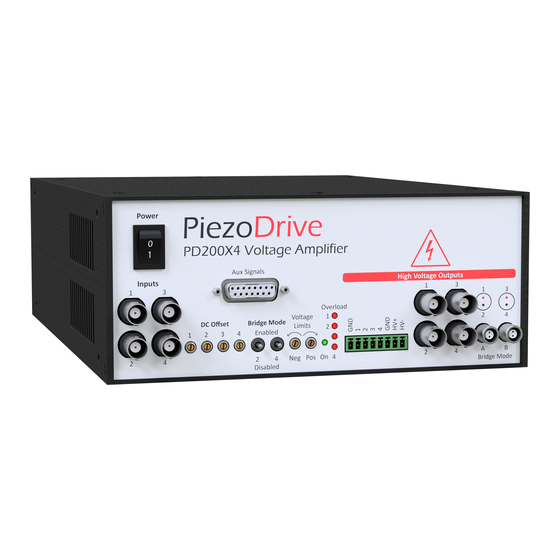
Page 14: Front Panel
The screw terminals or LEMO connector is recommended for applications requiring more than 1 Amp RMS output current. Preassembled LEMO cable assemblies (e.g. PD-0B302-W-120) are available from www.PiezoDrive.com The auxiliary signals connector is a 15-way DSUB receptacle (3M 8315-6000), it suits any 15-way male DSUB plug. -
Page 15: Voltage Limits
Signal Function Inputs 1, 2, 3, 4 Input for channels 1, 2, 3, 4 (+/-15V max) Voltage Monitor 5, 6, 7, 8 Voltage monitor for channels 1, 2, 3, 4. Gain = 1/20 V/V Current Monitor 9, 10, 11, 12 Current monitor for channels 1, 2, 3, 4. Gain = 1 V/A Disable A voltage between +3V and +24V shuts down the amplifier Fault... -
Page 16: Bias Outputs And Piezo Benders
-100V on HV+ and HV- respectively. For amplifier configurations where the HV- output is zero (e.g. PD200X4-V0,200), it is preferable to use ground rather than the HV- output. If specialized bias voltages are required, an amplifier output channel can be used with a DC offset. -
Page 17: Rear Panel
In Figure 10, the deflection is �� ���� �� = �� ���� where �� is the peak-to-peak displacement of the bender. ���� References A New Electrical Configuration for Improving the Range of Piezoelectric Bimorph Benders; S. A. Rios, A. J. Fleming; Sensors and Actuators A: Physical, 2015. 16 Rear Panel The power inlet suits an IEC C13 plug. -
Page 18: Options And Customization
PD200X4 amplifier with plug-in screw terminal installed IEC C13 power cable, suited to the shipping destination 20 Warranty PiezoDrive amplifiers are guaranteed for 12 months from the date of delivery. The warranty does not cover damage due to misuse. PD200X4 V2 Manual...
Need help?
Do you have a question about the PD200X4-V0,200 and is the answer not in the manual?
Questions and answers