Table of Contents
Advertisement
Quick Links
Programmable Driver Pack
Programmable Driver Pack
Programmable Driver Pack
Programmable Driver Pack
Programmable Driver Pack
#L010155
DPD75601
DPD75601
DPD75601
DPD75601
DPD75601
User's Guide
User's Guide
User's Guide
User's Guide
User's Guide
A N A H E I M A U T O M A T I O N , I N C .
A N A H E I M A U T O M A T I O N , I N C .
A N A H E I M A U T O M A T I O N , I N C .
A N A H E I M A U T O M A T I O N , I N C .
A N A H E I M A U T O M A T I O N , I N C .
910 East Orangefair Lane, Anaheim, CA 92801
e-mail: info@anaheimautomation.com
1
(714) 992-6990 fax: (714) 992-0471
website: www.anaheimautomation.com
July 2004
Advertisement
Table of Contents

Related Manuals for Anaheim Automation DPD75601


Summary of Contents for Anaheim Automation DPD75601
- Page 1 DPD75601 DPD75601 DPD75601 DPD75601 DPD75601 Programmable Driver Pack Programmable Driver Pack Programmable Driver Pack Programmable Driver Pack Programmable Driver Pack User’s Guide User’s Guide User’s Guide User’s Guide User’s Guide A N A H E I M A U T O M A T I O N , I N C .
-
Page 2: Table Of Contents
Table of Contents Table of Contents Table of Contents Table of Contents Table of Contents Section 1: Introduction Section 1: Introduction ................................................................................... 3 3 3 3 3 Section 1: Introduction Section 1: Introduction Section 1: Introduction ........................................................Description ................................ -
Page 3: Section 1: Introduction Section 1: Introduction
Description Description The driver in the DPD75601 (BLD75) is a step motor driver that cona drive motors rated from 1.0 to 7.0 amps/phase. It can handle 6-lead and 8-lead motors in a unipolar fashion. The DPD75601 features a unipolar bilevel (or dual voltage) drive technique with short circuit, open circuit, over voltage, under voltage and over temperature detection. -
Page 4: Electrical Specifications
Ordering Information Ordering Information The table below lists a variety of products available from Anaheim Automation, Inc. These products include those covered by this manual, along with supporting cables and devices. We are continually adding new products to our line, so please consult Anaheim Automation, Inc. or its representatives for information on the latest releases. -
Page 5: Dimensions/Switch Locations
Dimensions/Switch Locations Dimensions/Switch Locations Dimensions/Switch Locations Dimensions/Switch Locations Dimensions/Switch Locations Wiring Diagrams Wiring Diagrams Wiring Diagrams Wiring Diagrams Wiring Diagrams #L010155 July 2004... -
Page 6: Termianl Descriptions - Power
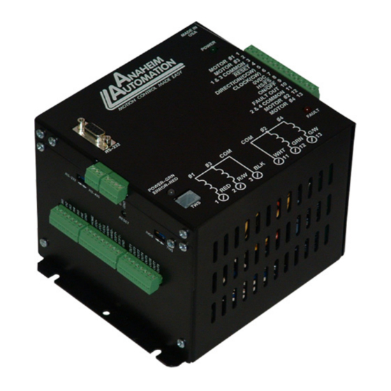
Termianl Descriptions - Power Termianl Descriptions - Power The DPD75601 is powered by an AC line voltages ranging from 90-265VAC. The following figure shows the various line voltages and the wiring for the power connection termianl block. Terminal Descriptions - Driver... -
Page 7: Terminal Descriptions - Controller
Terminal Descriptions - Controller Terminal Descriptions - Controller Terminal Descriptions - Controller Terminal Descriptions - Controller Terminal Descriptions - Controller t i s i r c t i s i r c ) - ( y l f t i s t i s i r c t i s... -
Page 8: Section 2: Driver Functions Section 2: Driver Functions
Section 2: Driver Functions Section 2: Driver Functions Section 2: Driver Functions Section 2: Driver Functions Section 2: Driver Functions Adjusting Kick Current Adjusting Kick Current Adjusting Kick Current Adjusting Kick Current Adjusting Kick Current By following the silkscreen instructions on the cover, use a small screwdriver to adjust the potentiometer. Line up the potentiometer’s arrow to the number corresponding to the motors rated current (amps/phase). - Page 9 Short (One Blink) Short (One Blink) Short (One Blink) Short (One Blink) Short (One Blink) This indicates that the driver or motor has a phase shorted or there is a “short” in the motor cable or wiring. Check the motor and the physical wiring for shorts. If the driver continues to sense shorts after the motor and wiring are determined to be accurate, then the output transistors should be checked using a multimeter as follows: 1.
-
Page 10: Section 3: Controller Functions Section 3: Controller Functions
RS232 Protocol - SW1 in RS232 position The DPD75601 is a DCE device, therefore it will transmit on pin 2 and receive on pin3 of the DB9 RS-232 connector . The RS232 serial communication mode is single ended. This means that for each signal there is one wire, and a common ground reference used by all the signals. -
Page 11: Axis Selection
RS232 to RS485 for multiple units or cables longer than 50ft The DPD75601 can be connected to your PC serial port via a RS485 converter ( model number: 485SD9TB sold separately ). This converter will convert the RS232 voltage signals to the compatible RS485 differential signals. - Page 12 Move to Position: The move to position command specifies the next absolute position to go to. The Move to Position: Move to Position: DPD75601 controller automatically sets the direction and number of steps needed to go to that posi- tion. (Range: -8388607 to +8388607) Slew:...
- Page 13 The speed however can not be changed when the DPD75601 is busy (moving). See examples below for calculations of the analog inputs. (Range of limits: 0 to 50000 and the lower limit < upper limit) Analog calculations.
- Page 14 Unless the finish move command is used, the DPD75601 will continue to execute the program. If it encounters a command that cannot be used when the motor is moving, the DPD75601 will error and stop the program prematurely.
- Page 15 Thumbwheel Index: This special function allows a thumbwheel with up to 7 decades to be used with the DPD75601 to set a relative index. To use the thumbwheel, SW2 must be in the TWS position or the thumbwheel will be disabled.
- Page 16 Section 4: SMC60WIN Software The SMC60WIN software is a handy utility that supports Anaheim Automation’s line of DPD75601’s step motor controllers. Connecting your PC to the DPD75601, via a serial cable, the SMC60WIN software can easily perform the following tasks: •...
-
Page 17: File Menu
F F F F F ile Menu ile Menu ile Menu ile Menu ile Menu t s i . . . t t n i Ex t i t i x S S S S S etup Menu etup Menu etup Menu etup Menu etup Menu... -
Page 18: Program Menu
P P P P P rogram Menu rogram Menu rogram Menu rogram Menu rogram Menu l l o . y r l l o . y r l l o . y r e l l . f f P P P P P rogram - rogram - rogram - rogram - A A A A A utostart Program Menu... -
Page 19: Help Menu
“The Unit is Connected” / “The Unit is NOT Connected” “The Unit is Connected” / “The Unit is NOT Connected” On the right of the Toolbar, the user will find the communication status of the DPD75601 controller. If communications are not established, please refer to the Troubleshooting Section. -
Page 20: Toolbar
Toolbar Toolbar Toolbar Toolbar Toolbar Exit Exit Exit Exit Exit Open Open Open Open Open Save Save Save Save Save Print Calculator Stop All Connect Print Calculator Stop All Connect Print Calculator Stop All Connect Print Calculator Stop All Connect Print Calculator Stop All Connect t i x t i x... -
Page 21: Tab Sheets - Real Time Motion
Tab Sheets - Real Time Motion Tab Sheets - Real Time Motion Tab Sheets - Real Time Motion Tab Sheets - Real Time Motion Tab Sheets - Real Time Motion & e l l e l l e l l e l l t i s t i s... -
Page 22: Tab Sheets - Encoder Options And Registration Inputs
Tab Sheets - Encoder Options and Registration Inputs Tab Sheets - Encoder Options and Registration Inputs Tab Sheets - Encoder Options and Registration Inputs Tab Sheets - Encoder Options and Registration Inputs Tab Sheets - Encoder Options and Registration Inputs . -
Page 23: Tab Sheets - Analog Input And Thumbwheel Options
Tab Sheets - Analog Input and Thumbwheel Options Tab Sheets - Analog Input and Thumbwheel Options Tab Sheets - Analog Input and Thumbwheel Options Tab Sheets - Analog Input and Thumbwheel Options Tab Sheets - Analog Input and Thumbwheel Options . -
Page 24: Tab Sheets - Create And Edit Program
With the create and edit program tab sheet selected, the user can obtain the amount of available memory, located to the right of the Delete command button. The DPD75601 has a maximum available memory of 2046 bytes - each instruction can use from 2 to 7 bytes. -
Page 25: Add/Change/Insert Commands
Currently Selected Line Currently Selected Line Currently Selected Line Currently Selected Line Currently Selected Line The currently selected line is indicated in the program by the right pointing arrow/triangle in the left column. Clicking on any line will select a new currently selected line. Add/Change/Insert Commands Add/Change/Insert Commands Add/Change/Insert Commands... -
Page 26: Add Tab Sheets - Motion Commands
Add Tab Sheets - Motion Commands Add Tab Sheets - Motion Commands Add Tab Sheets - Motion Commands Add Tab Sheets - Motion Commands Add Tab Sheets - Motion Commands & ) t r t i s t i s . -
Page 27: Add Tab Sheets - If/Then And Output Commands
Add Tab Sheets - If/Then and Output Commands Add Tab Sheets - If/Then and Output Commands Add Tab Sheets - If/Then and Output Commands Add Tab Sheets - If/Then and Output Commands Add Tab Sheets - If/Then and Output Commands o l l n i l n i l... -
Page 28: Add Tab Sheets - Goto, For Loops, Encoder And Thumbwheel Commands
Add Tab Sheets - Goto, For Loops, Encoder and Thumbwheel Commands Add Tab Sheets - Goto, For Loops, Encoder and Thumbwheel Commands Add Tab Sheets - Goto, For Loops, Encoder and Thumbwheel Commands Add Tab Sheets - Goto, For Loops, Encoder and Thumbwheel Commands Add Tab Sheets - Goto, For Loops, Encoder and Thumbwheel Commands o l l f i c... -
Page 29: Add Tab Sheets - Analog, Registration And Text Commands
Add Tab Sheets - Analog, Registration and Text Commands Add Tab Sheets - Analog, Registration and Text Commands Add Tab Sheets - Analog, Registration and Text Commands Add Tab Sheets - Analog, Registration and Text Commands Add Tab Sheets - Analog, Registration and Text Commands ) f f . -
Page 30: Calculator
Calculator Calculator Calculator Calculator Calculator > - t u l > - t u l t u l t l u t i x #L010155 July 2004... -
Page 31: Section 5: Direct Talk Mode
Section 5: Direct Talk Mode Direct mode is used to directly control motion for real time movements through serial communication. The DPD75601 controller has 40 commands, which are easy to remember for direct movement of a step motor. COM Port Settings... - Page 32 A - Acceleration/Deceleration A - Acceleration/Deceleration A - Acceleration/Deceleration A - Acceleration/Deceleration A - Acceleration/Deceleration Format: A[value] Description: This command sets the acceleration profile which is an integer value between 100 and 9,999,999. The higher the value, the faster the motor acceleration. Range: 100 - 9,999,999 B - Base speed...
- Page 33 ER -Encoder retries ER -Encoder retries Format: ER[value] Description: This is the number of times the DPD75601 controller will try to autocorrect the motor before erroring. This command is used in conjunction with the encoder autocorrect EA command. Range: 0 - 255...
- Page 34 Format: Description: This command is used to send a set number of clocks out of the DPD75601 controller. An N or P command must be entered before the G command. The ramp profile is specified by the B (base speed), M (max speed), and A (accelera- tion/ deceleration) commands.
- Page 35 N[value] Description: This command sets the number of clocks for the DPD75601 to send out following a G command. It is also used to set the registration index during and index on the fly move. Motion is not activated by this command; it only sets the index register.
- Page 36 This command uses the voltage on input 1 to calculate and set the number of clocks for the DPD75601 to send out following a G command. The analog position must be enabled for this command to work. Motion is not activated by this com- mand, it only sets the register (N = P - Z).
- Page 37 ! - Error codes register Format: Description: This command requests the DPD75601 controller to get the current error code and print it to the screen. For a description of the error codes see page 39. $ - Version number register...
- Page 38 In a slew type motion the DPD75601 controller will ramp down and stop. In a home type motion the DPD75601 controller will ramp down and run at base speed, until the home limit is activated.
- Page 39 / - Thumbwheel index enabled / - Thumbwheel index enabled / - Thumbwheel index enabled / - Thumbwheel index enabled / - Thumbwheel index enabled Format: /[0 or 1] Description: This command will either enable or disable the ability to use the thumbwheel switches for indexing.
- Page 40 ~ - Set address register ~ - Set address register Format: ~[value] (No address is needed before this function. @~[value] will set the address) Description: This command set the address for communication inside the DPD75601 controller. Range: 0 - 99 #L010155 July 2004...
-
Page 41: Section 6: Troubleshooting
Possible Solutions: Possible Solutions: Possible Solutions: 1) Make sure the DPD75601 controller has power. Is the controller’s Green LED on? 2) Check the RS232/RS485 connections. 3) Check for loose cable connections either on the DPD75601 controller or COM Port. 4) Was the software installed successfully? -
Page 42: Error Codes
1) Verify your program for improper syntax that may cause an error code. 2) Physically press the reset button on the DPD75601 to clear an error. 3) Another way to clear an error is by using either the SMC60WIN software or the direct mode command instructions set. -
Page 43: Section 7: Sample Program Section 7: Sample Program
Section 7: Sample Program Section 7: Sample Program Section 7: Sample Program Section 7: Sample Program Section 7: Sample Program Sample Program 1: Sample Program 1: Sample Program 1: Sample Program 1: Sample Program 1: Sample Program 1 illustrates a typical application where a system moves to a specific position required. The sample program shows how to use the motion and goto instruction commands. -
Page 44: Sample Program 2
Sample Program 2: Sample Program 2: Sample Program 2: Sample Program 2: Sample Program 2: Sample Program 2 illustrates a typical application where a system is first sent home to a datum or 0 position. This sample program shows how a motor will move to 3 different positions utilizing some of the motion commands, loop routines and encoder routine. -
Page 45: Sample Program 3
Sample Program 3: Sample Program 3: Sample Program 3: Sample Program 3: Sample Program 3: Sample Program 3 illustrates the setup and operation of the output on the fly function, and the use of the if/then statement. The system is first homed using home type 0, waits for input 1 to be a value of 0 (grounded) and then is indexed 10,000 steps. -
Page 46: Sample Program 4
Sample Program 4: Sample Program 4: Sample Program 4: Sample Program 4: Sample Program 4: Sample Program 4 illustrates the setup of the analog speed function and the use of “indexing-on-the-fly.” The system is first homed using home type 1. The next step is to wait for the input register to read 110111 (input 2 must be high while input 3 is low, all other inputs are not used and input 1 is masked high due to the analog function being used). -
Page 47: Sample Program 5
Sample Program 5: Sample Program 5 illustrates a typical 3 axis application where one DPD75601 (Axis 0) is controlling the other two axes (Axis 1 and Axis 2) by using the send text string commands. The program first sets the accelerations, base speeds and maximum speeds for each axis. -
Page 48: Appendix 1: Ascii Table For Direct Mode
Appendix 1: ASCII Table for Direct Mode Appendix 1: ASCII Table for Direct Mode Appendix 1: ASCII Table for Direct Mode Appendix 1: ASCII Table for Direct Mode Appendix 1: ASCII Table for Direct Mode " #L010155 July 2004... - Page 49 Anaheim Automation, Inc. will repair or replace at its option, any of its products which have been found to be defective and are within the warranty period, provided that the item is shipped freight prepaid, with RMA (return material authorization), to Anaheim Automation’s plant in Anaheim, California.
Need help?
Do you have a question about the DPD75601 and is the answer not in the manual?
Questions and answers