Table of Contents
Advertisement
Quick Links
Advertisement
Table of Contents

Related Manuals for Anaheim Automation DPE25611


Summary of Contents for Anaheim Automation DPE25611
- Page 1 DPE25611 Programmable Driver Pack User’s Guide A N A H E I M A U T O M A T I O N 4985 E. Landon Drive Anaheim, CA 92807 (714) 992-6990 fax: (714) 992-0471 e-mail: info@anaheimautomation.com website: www.anaheimautomation.com July 2018...
-
Page 2: Table Of Contents
Table of Contents Section 1: Introduction..........................3 Description..............................3 Electrical Specifications..........................4 Ordering Information............................4 Dimensions/Switch Locations........................5 Wiring Diagrams............................5 Terminal Descriptions - Driver.........................6 Terminal Descriptions - Controller......................6 Connector Descriptions - Controller.........................6 Slide Switch Descriptions - Controller......................6 Section 2: Driver Functions..........................7 Motor Selection.............................7 Step Motor Current Setting Guide......................7 Setting the Output Current..........................7 Reducing Output Current..........................8 Determining Output Current...........................8... -
Page 3: Description
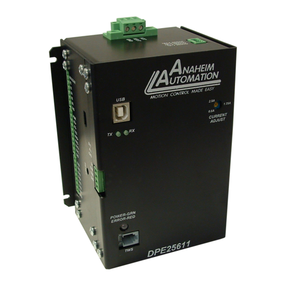
The DPE25611 can be powered from 100-240 VAC, 50/60Hz. Description The driver in the DPE25611 (MBC25081) is a microstep motor driver that can drive motors rated from 0.5 to 2.5 amps/phase. It can handle 4, 6 and 8-lead motors in a bipolar fashion. The DPE25611’s driver features motor current ON/OFF capabilities and a Reduced Current Enabled... -
Page 4: Electrical Specifications
DPE25611 for autostart use, and also upload the program that is stored in the DPE25611 itself for editing and viewing. The software also allows you to save the programs onto your computer hard drive, and easily retrieve them when needed. -
Page 5: Wiring Diagrams
Dimensions Wiring Diagrams July 2018 L010796 August 2012... -
Page 6: Terminal Descriptions - Driver
Terminal Descriptions - Driver Position Description - Motor Connection Phase A: Phase 1 of the Step Motor Phase Ā: Phase 3 of the Step Motor Phase B: Phase 2 of the Step Motor Phase B: Phase 4 of the Step Motor Terminal Descriptions - Controller Position Description - Encoder... -
Page 7: Section 2: Driver Functions
Since the DPE25611 is a constant current source, it is not necessary to use a motor that is rated at the same voltage as the supply voltage. What is important is that the driver is set to the ap- propriate current level based on the motor being used. -
Page 8: Reducing Output Current
The output current for the motor used when microstepping is determined differently from that of a full/half step unipolar driver. In the DPE25611, a sine/cosine output function is used in rotating the motor. The output current for a given motor is determined by the motors current rating and the wiring configuration of the motor. -
Page 9: Connecting The Step Motor
4 Lead Motors Multiply the specified series motor current by 1.4 to determine the current adjustment potentiom- eter value. Four lead motors are usually rated with their appropriate series current, as opposed to the Phase Current, which is the rating for 6 and 8 lead motors. 8 Lead Motors Series Connection: When configuring the motor windings in series, use the per phase (or uni- polar) current rating to determine the current setting potentiometer value. -
Page 10: Section 3: Controller Functions
For example: A DPE25611 can replace simple motion control and replace I/O functional when minimal quantities of I/O are required to control specific machinery. Simple motion profiles that can operate with 6 or less inputs and 8 or less outputs can utilize a DPE25611 controller. Baud Rate A term used frequently is serial data communications, a “baud”... - Page 11 This command will move the motor the number of steps given. (Range: 1 to 8388607) Move to Position: The move to position command specifies the next absolute position to go to. The DPE25611 controller automatically sets the direction and number of steps needed to go to that posi- tion. (Range: -8388607 to +8388607) Slew: The slew command will accelerate the motor up to maximum speed and continue to run at that speed until reaching a registration mark, hard limit switch, soft limit switch, receiving a “.”...
- Page 12 The speed however can not be changed when the DPE25611 is busy (moving). See examples below for calculations of the analog inputs. (Range of limits: 0 to 50000 and the lower limit < upper limit)
- Page 13 Finish Move: When writing a program, the finish move command is used directly after every motion com- mand. When using this command, the DPE25611 internally generates a busy signal and will wait until the move is complete before executing any further commands. Unless the finish move command is used, the DPE25611 will continue to execute the program.
- Page 14 Thumbwheel Index: This special function allows a thumbwheel with up to 7 decades to be used with the DPE25611 to set a relative index. To use the thumbwheel, SW2 must be in the TWS position or the thumbwheel will be disabled.
-
Page 15: Section 4: Smc60Win Software
Section 4: SMC60WIN Software The SMC60WIN software is a handy utility that supports Anaheim Automation’s line of DPE25611’s step motor controllers. Connecting your PC to the DPE25611, via a serial cable, the SMC60WIN software can easily perform the following tasks: •... -
Page 16: File Menu
File Menu New Program Start editing a new program. Open Program Open an existing program from disk. Save Program As Save the current program to disk. Print... Print the current program. Exit Exit the SMC60WIN software. Setup Menu Connect Establish communications with the controller. Disconnect Release the COM port for other devices to use. -
Page 17: Program Menu
Program Menu Start Program Start the execution of the program in the controller memory. Stop Program Stop the execution of the program in the controller memory. View Program View the program stored in the controller memory. Clear Program Memory Clear the program memory in the controller. Autostart Program Turn the autostart function on or off. -
Page 18: Help Menu
Displays the version of the SMC60WIN and contact information. “The Unit is Connected” / “The Unit is Not Connected” On the right of the Toolbar, the user will find the communication status of the DPE25611 controller. If communications is not established, please refer to the troubleshooting section. -
Page 19: Toolbar
Monitor and change settings for encoder options, input on the fly and output on Registration Inputs the fly. Analog Input and Monitor and change settings to Analog Inputs and the thumbwheel switches. Thumbwheel Options Create and Edit Pro- Write and edit DPE25611 stored programs. grams July 2018 L010796 August 2012... - Page 20 Tab Sheets - Real Time Motion Set Accel/Decel Send acceleration & deceleration parameter to controller. (step/sec Set Base Speed Send base speed parameter to the controller. (step/sec) Set Max Speed Send maximum speed parameter to the controller. (step/sec) Set Jog Speed Send fast jog speed parameter to the controller.
- Page 21 Tab Sheets - Encoder Options and Registration Inputs Encoder Auto Correct Set the encoder auto correct feature on or off. Set Encoder Delay Send the encoder delay parameter to the controller. (ms) Set Motor Ratio Send the encoder pulse to motor step ratio to the controller. Send number of encoder auto correct retries to the controller.
- Page 22 Tab Sheets - Analog Input and Thumbwheel Options Analog Max Speed Input Sets the analog speed input feature on or off. Set Speed Lower Limit Send the analog speed lower limit to the controller. Set Speed Upper Limit Send the analog speed upper limit to the controller. Set Analog Speed Sets the max speed based on analog voltage measured at input.
- Page 23 With the created and edit program tab sheet selected, the user can obtain the amount of available memory, located to the right of the Delete command button. The DPE25611 has a maximum available memory of 2046 bytes - each instruction can use from 2 to 7 bytes.
-
Page 24: Add/Change/Insert Commands
Currently Selected Line The currently selected line is indicated in the program by the right pointing arrow/triangle in the left column. Clicking on any line will select a new currently selected line. Add/Change/Insert Commands The Add/Change/Insert commands contain four different tab sheets, which are “Motion Com- mands”, “If/Then and Output Commands”, “Goto, For Loops, Encoder and Thumbwheel Com- mands”... - Page 25 Add Tab Sheets - Motion Commands Accel/Decel Set program acceleration & deceleration parameter. (step/sec Base Speed Set program base (start) speed rate. (step/sec) Max Speed Set program maximum (running) speed rate. (step/sec) Set Jog Speed Set program jogging speed rate. (step/sec) Set Position Set motor position.
- Page 26 Add Tab Sheets - If/Then and Output Commands If inputs match below then This conditional command allows the user to execute the next line of code if execute the next line, other- the inputs triggered match the given value. If the inputs do not match, the next wise skip the next line line is skipped.
- Page 27 Add Tab Sheets - Goto, For Loops, Encoder and Thumbwheel Commands Goto Command allows the program to jump to the specified label. Label Command inserts a label for go to and loop commands. Return from Subroutine Command will return to the last goto and execute the next line of code. Command allows a sequence of commands to be looped a specific number Outer Loop of times to a label.
- Page 28 Add Tab Sheets - Analog, Registration and Text Commands Analog Speed On (Off) Sets the analog speed input feature on or off. Set Analog Speed Sets the maximum (running) speed based on the analog input. Analog Speed Lower Limit Sets the analog speed lower limit to the value specified. Analog Speed Upper Limit Sets the analog speed upper limit to the value specified.
-
Page 29: Calculator
Calculator PPS -> RPS Convert from pulses per second to revolution per second. RPS ->PPS Convert from revolution per second to pulses per second. Enter the number of steps per revolution of the step motor. The default is for a Steps Per Rev 200 step/rev motor in half step, which is equal to 400. -
Page 30: Section 5: Direct Talk Mode
Section 5: Direct Talk Mode Direct mode is used to directly control the motion for real time movements through serial communica- tion. The DPE25611 controller has 40 commands which are easy to remember for direct movement of a step motor. - Page 31 A - Acceleration/Deceleration Format: A[value] Description: This command sets the acceleration profile which is an integer value between 100 and 9,999,999. The higher the value, the faster the motor acceleration. Range: 100 - 9,999,999 B - Base Speed Format: B[value] Description: This command sets the base (start) speed for motion.
- Page 32 ER[value] Description: This is the number of times the DPE25611 controller will try to auto correct the motor before an error occurs. This command is used in conjunction with the encoder auto correct EA command. When the auto correct error, Output 8 will be triggered.
- Page 33 Format: Description: This command is used to send a set number of clocks out of the DPE25611 controller. An N or P command must be entered before the G command. The ramp profile is specified by the B (base speed), M (max speed), and A (acceleration/deceleration) com- mands.
- Page 34 This command reads the thumbwheel switches to set the number of clocks for the DPE25611 to send out following a G command. For this command to work SW2 must be in the TWS position, and the thumbwheel enable bit must be enabled. Motion is not activated by this command, it only sets the index register.
- Page 35 This command uses the voltage on input 1 to calculate and set the number of clocks for the DPE25611 to send out following a G command. The analog position must be enabled for this command to work. Motion is not activated by this command, it only sets the register (N = P - Z).
- Page 36 ! - Error Codes Register Format: Description: This command requests the DPE25611 controller to get the current error code and print it to the screen. For a description of the error codes see page 39. $ - Version Number Register...
- Page 37 In a relative or absolute type motion the DPE25611 controller will continue to the set position and stop. In a slew type motion the DPE25611 controller will ramp down and stop. In a home type motion the DPE25611 controller will ramp down and run at base speed, until the home limit is activated.
- Page 38 / - Thumbwheel Index Enabled Format: /[0 or 1] Description: This command will either enable or disable the ability to use the thumbwheel switches for indexing. If enable, SW2 must be in the TWS position for the thumbwheel to be connected to the processor. : - Analog Position Enabled Format: :[0 or 1]...
- Page 39 ~ - Set Address Register Format: ~[value] (No address is needed before this function. @ ~[value] will set the address) Description: This command sets the address for communication inside the DPE25611. Range: 0 - 99 July 2018 L010796 August 2012...
-
Page 40: Section 6: Troubleshooting
Can not establish communications with the DPE25611. Possible Solutions: 1. Make sure the DPE25611 controller has power. Is the controller’s Green LED on? 2. Check RS232/RS485 connections. 3. Check for loose cable connection either on the DPE25611 controller or COM Port. -
Page 41: Errors Codes
1. Verify your program for improper syntax that may cause an error code. 2. Physically press the reset button on the DPE25611 to clear an error. 3. Another way to clear an error is by using either the SMC60WIN software or the direct mode command instructions set. -
Page 42: Section 7: Sample Programs
Section 7: Sample Programs Sample Program 1: Sample Program 1 illustrates a typical application where a system moves to a specific position required. The sample program shows how to use motion and go to instruction commands. July 2018 L010796 August 2012... - Page 43 Sample Program 2: Sample Program 2 illustrates a typical application where a system is first sent home to a datum or 0 position. This sample program shows how a motor will move to a 3 different positions utilizing some of the motion commands, loop routines and encoder routine. July 2018 L010796 August 2012...
- Page 44 Sample Program 3: Sample Program 3 illustrates the setup and operation of the output on the fly function, and the use of the if/then statement. The system is first home using home type 0, waits for input 1 to be a value of 0 (grounded) and then is indexed 10,000 steps.
- Page 45 Sample Program 4: Sample Program 4 illustrates the setup of the analog speed function and the use of “indexing- on-the-fly.” The system is first homed using home type 1. The next step is to wait for the input register to read 110111 (input 2 must be high while input 3 is low, all other inputs are not used and input 1 is masked high due to analog function being used).
- Page 46 Sample Program 5: Sample Program 5 illustrates a typical 3 axis application where one DPE25611 (Axis 0) is control- ling the other two axes (Axis 1 and Axis 2) by using the send text string commands. The program first sets the accelerations, base speeds and maximum speeds for each axis. It then is enabling Axis 0 and Axis 1 to use the thumbwheel switch that is connected to each unit for indexing.
-
Page 47: Appendix 1: Ascii Table For Direct Mode
Appendix 1: ASCII Table for Direct Mode ASCII Symbol Hex Value ASCII Symbol Hex Value ASCII Symbol Hex Value “ Carriage Return Appendix 2: Firmware Revisions Versions 1.00 - Initial Release. Versions 1.10 - Fixes lockup on RS485 Communication. Added capability to stop the motor on an Encoder Error after the Encoder Retries number has been reached. - Page 48 Anaheim Automation will repair or replace at its’ option, any product which has been found to be defective and is within the warranty period, provided that the item is shipped freight prepaid, with previous authorization (RMA#) to Anaheim Automation’s plant in Anaheim, California.
Need help?
Do you have a question about the DPE25611 and is the answer not in the manual?
Questions and answers